Hi all - I'm hoping for some suggestions about how best to power 2 X 140mm chassis fans for cooling the filament shunt regulator boards in my 300B preamp. I can't post a schematic for intellectual property rights reasons, but the schematic is irrelevant to my question. Suffice it to say that the shunt reg circuit is designed with very tight tolerances for putting out 10V DC @ 1.2A (only 5V of which is dropped across the filaments - the 300Bs are filament biased). And I am using EML 300Bs which draw 1.3A - and this is putting some heat stress on the regulators. I've looked into increasing the size of the heatsink, but there is only one bigger that will fit, and its datasheet suggests that it would offer only marginal improvement in heat dissipation.
... So I'm going to experiment with forced air. My question is how best to power them? I'm worried that their motors might inject noise into the amp via the power supply. I don't know if they would or could in fact do so (I'm still very much a noob), and would appreciate any insight that you all might have on this more fundamental issue as well.
The options I see are:
(1) battery power - completely disconnected from the amp's power supplies (HV and fil), and quiet in any event. Downside: will require frequent recharging of batteries; and seems a bit inelegant.
(2) Seperate 12V DC supply connected to the mains wall outlet - diy or ready-made.
(3) internal 12V DC supply (trafo, recitifer and smoothing circuit) that taps the mains supply coming into the amp that also supplies the HV and filament transformers (I'm installing dedicated filament transformers to get a bit more raw voltage from the secondaries - the voltage form the existing heater windings is a bit low).
(4) power them from the new 12.6VAC filament supplies (rectified and smoothed to 13.5VDC for feeding the shunt regulators) - by way of a dropping resistors.
In case it is relevant, I'll add that the HV has a CLCLC filter, the Fil supply will have a CLC filter, and both the 300B B+ and the filament DC are shunt regulated. So there's a lot to isolate the signal wiring from any noise at the beginning of the power supplies. But I am a bit paranoid about noise 🙂
I should also add that I recognize that vibration transmitted to the chassis could be an issue and plan to damp that by mounting the fans on the open underside of the enclosure via a trampoline-type suspension - basically on rubber bands.
Any thoughts, insights, suggestions?
many thanks in advance,
Derek
Last edited:
1 regulator with 1 heatsink per filament - the regulator is the LM1085
Ok, you've already spread out the dissipation as much as possible.
Are there preregulators before the shunt regulators?
Can you post a general block diagram of the filament supply?
Apologies - I missed the question about other power supplies. The C4S/shunt reg boards for B+, 1 per channel, also have 2 heatsinks each (I believe they are the same as the ones used on the LM1085s).
So there are 6 existing heatsinks in total.
So there are 6 existing heatsinks in total.
Apologies - I missed the question about other power supplies. The C4S/shunt reg boards for B+, 1 per channel, also have 2 heatsinks each (I believe they are the same as the ones used on the LM1085s). So there are 6 existing heatsinks in total.
Can you post a general block diagram?
Last edited:
Are there preregulators before the shunt regulators?
I don't know what a preregulator is - can you explain?
But I should emphasize that I want to do the forced air experiment. I like tinkering and want to see if it can be made to work - even if additional heatsinking is possible. If it doesn't work, it can easily be removed. So this is where my focus is at the moment.
cheers and thanks, Derek
I don't know what a preregulator is - can you explain?
But I should emphasize that I want to do the forced air experiment. I like tinkering and want to see if it can be made to work - even if additional heatsinking is possible. If it doesn't work, it can easily be removed. So this is where my focus is at the moment.
Sure, how will the air flow if the sinks are installed on a pcb, are the boards vertical?
If so, are the sinks mounted so their wide dimension will be vertical also?
Do you have an infrared temperature gun?
A preregulator fixes the input voltage to a regulator, so the regulator dissipation can be minimized,
without having to take into account line voltage variation.
Last edited:
In a Power amp, the acoustic blow-noise is likely to be more offensive than EMI noise.
Two 6-inch fans seems overkill for a mere 12W of waste heat to haul away. (Which does mean you can spin them at 25% speed and maybe 10% of stock noise...)
Two 6-inch fans seems overkill for a mere 12W of waste heat to haul away. (Which does mean you can spin them at 25% speed and maybe 10% of stock noise...)
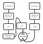
Here is my stab at a basic block diagram - this info is already published by the designers, but I can't disclose any more detail. I respect their intellectual property (and they are great people and I wouldn't want to do anything that might hurt their interests).
In stock configuration all heatsinks are mounted facing downwards lengthwise on the outer edges of pcbs that are the width of the heatsinks. The pcbs are mounted parallel to the chassis on 1 1/2"-ish standoffs below or near vent slits cut in the chassis top plate. The bottom of the enclosure is totally open.
I don't have a IR gun, but do have a thermocouple - but this is of no present use because I've already stripped the amp in preparation for rebuilding it on a much bigger chassis (the CLCLC filter I added took up a lot of space, as did some giant caps - which undoubtedly limited free air flow). But I am in contact with the designers and they have suggested that using EML 300Bs with their 1.3A filament draw rather than normal 1.2A 300B may be causing some heat stress.
I don't think it has a preregulator - I think the voltage feeding the regulator is dependent on the raw voltage from the secondary filament winding. If the mains voltage drops below about 117VAC, the reg drops out and I get a lot of hum. Bump up mains to above 117VAC with a Variac and the hum disappears. But this is with the EML 300B tubes. The fil reg seemed less sensitive to mains voltage fluctuations when using a standard 1.2A draw 300B.
Attachments
I should add that the goofiness of adding CLCLC and CLC filters in front of shunt regs and C4S/shunt regs is my goofiness, not the designers'. I've already been told that replacing all the RC's with LCs would do nothing bc the impedance to AC of the chokes is dwarfed by the impedance of the C4Ss. I've added these just because that's the stage I've reached in my tube circuit learning: I recently figured out how to model in PSUD and have been happily busy (unnecessarily) adding CLC-type filters to all my amps. 🙂 I'll grow out of it once I learn how to do something more sophisticated/educated.
cheers, Derek
cheers, Derek
power it off the shunt regulator supply and put a dropping resistor inline to slow it down.
That makes sense, but the shunt reg is already having a hard time with the 1.3A draw of the EML 300Bs. Each fan would draw an additional 0.3A at full power.
In a Power amp, the acoustic blow-noise is likely to be more offensive than EMI noise.
)
Do you mean the wind sound of the air moving over the components? I powered up the fans this evening to test them and they don't blow all that hard - about 100 CFM @ 1000 rpm. Holding my spread fingers over the fans, I couldn't hear anything. Or does the blow-noise somehow become part of signal - e.g., by causing vibrations?
As for motor noise, the manufacturer specs state max 15.5 dB(A). I can barely hear them.
many thanks, Derek
I've a little bit of experience with this sort of things having had to use a couple of fans to cool a couple of big monoblocks. having fitted one fan there was no injected noise at all, but the fan itself was noticeable at low volume.
I tried powering from the 12.6v heater supply with a 100 ohm dropper to slow fan speed and hence noise but in the end used a 10v SMPSU brick ; there was no noise issue's. I'd recommend trying a temporary solution and seeing how you go. I re-used the big ferrite that came with the SMPSU on the mains IP. My amp uses shielded two core with the red as hot, blue as signal ground, grounded right on the IP valve grid leak resistor, the shield is also grounded there and there only.
So, in brief, if your shielding and grounding is good, I think you should be ok.
Andy.
Use any available 12 ( 3 or 4 ). A small resistor in series will reduce fan speedHi all - I'm hoping for some suggestions about how best to power 2 X 140mm chassis fans for cooling the filament shunt regulator boards in my 300B preamp. I can't post a schematic for intellectual property rights reasons, but the schematic is irrelevant to my question. Suffice it to say that the shunt reg circuit is designed with very tight tolerances for putting out 10V DC @ 1.2A (only 5V of which is dropped across the filaments - the 300Bs are filament biased). And I am using EML 300Bs which draw 1.3A - and this is putting some heat stress on the regulators. I've looked into increasing the size of the heatsink, but there is only one bigger that will fit, and its datasheet suggests that it would offer only marginal improvement in heat dissipation.
... So I'm going to experiment with forced air. My question is how best to power them? I'm worried that their motors might inject noise into the amp via the power supply. I don't know if they would or could in fact do so (I'm still very much a noob), and would appreciate any insight that you all might have on this more fundamental issue as well.
The options I see are:
(1) battery power - completely disconnected from the amp's power supplies (HV and fil), and quiet in any event. Downside: will require frequent recharging of batteries; and seems a bit inelegant.
(2) Seperate 12V DC supply connected to the mains wall outlet - diy or ready-made.
(3) internal 12V DC supply (trafo, recitifer and smoothing circuit) that taps the mains supply coming into the amp that also supplies the HV and filament transformers (I'm installing dedicated filament transformers to get a bit more raw voltage from the secondaries - the voltage form the existing heater windings is a bit low).
(4) power them from the new 12.6VAC filament supplies (rectified and smoothed to 13.5VDC for feeding the shunt regulators) - by way of a dropping resistors.
In case it is relevant, I'll add that the HV has a CLCLC filter, the Fil supply will have a CLC filter, and both the 300B B+ and the filament DC are shunt regulated. So there's a lot to isolate the signal wiring from any noise at the beginning of the power supplies. But I am a bit paranoid about noise 🙂
I should also add that I recognize that vibration transmitted to the chassis could be an issue and plan to damp that by mounting the fans on the open underside of the enclosure via a trampoline-type suspension - basically on rubber bands.
Any thoughts, insights, suggestions?
many thanks in advance,
Derek
and any EMI. I don't expect the fans to inject EMI in disturbing amounts.
FWIW, a way to hold moving air noise down is by employing good sized cheap "240" VAC fans on 120 VAC. Lots of air moving slowly is the result.
Ηi Derek
look at the pic , i m feeding a circuit with Attiny 85 chip (slow to fast speed )-two fan option 12V 4cmX4cm fan ,from main cap of the L-Adapter circuit ,no noise at all ,activated at 42C and keeps cool the input heatsink reg HV Salas .....
6V6 line preamp
look at the pic , i m feeding a circuit with Attiny 85 chip (slow to fast speed )-two fan option 12V 4cmX4cm fan ,from main cap of the L-Adapter circuit ,no noise at all ,activated at 42C and keeps cool the input heatsink reg HV Salas .....
6V6 line preamp
Last edited:
- Home
- Amplifiers
- Tubes / Valves
- Best way of powering 12V DC chassis fans?