I know that’s part of it. Like 92dB at 1w/1m is about twice as loud. Previously to the F5T I was using a class D 2x100w (@4ohm) amp board with the dsp and speaks. Lots of volume. I’m not sure what the voltage gain of that amp is, but it lists gain at 30dB. The f5t ver. 2 that I built should have 20dB.
I will say that there is more bottom end and better clarity with the f5t. I’m not going to switch back, but I’m surprised, at how quiet it is. I’ll keep poking around. I’ll get some measurements soon.
I will say that there is more bottom end and better clarity with the f5t. I’m not going to switch back, but I’m surprised, at how quiet it is. I’ll keep poking around. I’ll get some measurements soon.
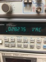
My F5T had noise measurements around -88 dB and lower, except for one channel's 120 Hz reading.
I moved a secondary circuit board to a different place, and it should have lowered it further. I will report when complete, but having some issues with one channel at the moment.
I moved a secondary circuit board to a different place, and it should have lowered it further. I will report when complete, but having some issues with one channel at the moment.
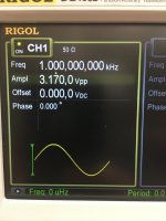
Well it’s confirmed 0.9vrms output from the dsp is not enough. I bypassed that and scrambled for the down button on my iPhone. We have enlightenment. Although I don’t know the output specs of that old iPhone 5s.
The FNG
Okay, I just want to make sure I got my mind around what 6L6 was saying in:
Testing and Powerup
Adjustments (Bias and Offset, set with P1 and P2)
This is easiest with three DMM.
Shorting the input jacks is helpful, although not strictly necessary.
Before power up, dial pots P1 and P2 to 0 ohms ( check with ohmmeter across TP1-2 and TP3-4 on FE board )
With voltmeter across PSU output ( best between + and - of PSU) observe max voltage of PSU - it never hurts to make sure it’s doing what you expect.
Place one voltmeter at output - to observe DC offset
Place voltmeters across TP of output board, one on N-channel, one on P channel.
Okay, so using the DIY v3 boards, I would have one meter from TP1 on either N or P board to ground for offset voltage and one meter each on T2-T3 on both N and P channels?
Looks at the voltage across the source on both N&P and the offset is from TP1 to ground?
Last edited:
one dvm from output to gnd , to observe DC output offset
second dvm across any output source resistor
no need for third dvm
second dvm across any output source resistor
no need for third dvm
With black lead on psu GND, make sure you have Vneg and Vpos on the PSU where you expect and at the proper voltage.
ZM is correct, you don’t need the third DMM, but it is nice to have to see their relationship between both halves of the amp.
ZM is correct, you don’t need the third DMM, but it is nice to have to see their relationship between both halves of the amp.
@ Zen
Makes perfect sense to me as both TP2s are at electrically the same point and since both resistors are of the same value, what one sees the other also sees.
@6L6
Thanks for your thinking on this as I was somewhat confused as to why the 3 meters. I shall verify source voltages at the wires before install on the + & - sides. I also do have 3 meters, so it's really no hardship to just clip on two gators.
Thanks Zen
Last edited:
It was long time with no posts here and I’m happy to see some guys got back to the project.
I appreciate advises and guides from 6L6 towards my last update on F5T v.3 mono blocks.
I got 54 Watt out (6R impedance) on my mono blocks by using 25VAC transformer. So, 30-32 volt DC on my PSU allowed me that power out and 470mV BIAS (about 1A CC) was set according to the heat sink MAX temperate allowed.
Now about upgrade… My speakers optimum power setup required about 80W or more (it was advice from speaker designer) and I tried to push my amp further.
New transformer is used and it is AN-8435 from AnTek. It is 35VAC which brought me to about 45-46VDC on PSU. Luckily, my PSU Ele caps are rated for 50V and I did not exceeded their MAX.
I was supposed to drop BIOS and left it at 360mV with about 55 deg C on sinks.
I have 132W (28dB gain) now and my speakers are very “happy”. I see no change in distortion level and got abut same readings from distortion analyzer during P3 setup to same style as I set it before PSU upgrade –> 0.03%.
Attachments
@ Alex... Sweet! I think you mean bias and not BIOS lol. I'm an old computer guy and make the mistake myself. 😛
JT
JT
@ Alex... Sweet! I think you mean bias and not BIOS lol. I'm an old computer guy and make the mistake myself. 😛
JT
Thank you JT. Yes, it is Bias. 🙂
That sunds good. I did expect the distortion to og up a bit. With your original setup, you would have reach about 75W class A/B. And it would stay inn class A a bit longer then what it do now.It was long time with no posts here and I’m happy to see some guys got back to the project.
I appreciate advises and guides from 6L6 towards my last update on F5T v.3 mono blocks.
I got 54 Watt out (6R impedance) on my mono blocks by using 25VAC transformer. So, 30-32 volt DC on my PSU allowed me that power out and 470mV BIAS (about 1A CC) was set according to the heat sink MAX temperate allowed.
Now about upgrade… My speakers optimum power setup required about 80W or more (it was advice from speaker designer) and I tried to push my amp further.
New transformer is used and it is AN-8435 from AnTek. It is 35VAC which brought me to about 45-46VDC on PSU. Luckily, my PSU Ele caps are rated for 50V and I did not exceeded their MAX.
I was supposed to drop BIOS and left it at 360mV with about 55 deg C on sinks.
I have 132W (28dB gain) now and my speakers are very “happy”. I see no change in distortion level and got abut same readings from distortion analyzer during P3 setup to same style as I set it before PSU upgrade –> 0.03%.
But i realy hope you cascoded the input J-fet's 🙂
Yes, my inputs are cascoded. I noticed that my low end punch is better now during “crescendo” moments. I have Acoustic Zen speaker and they are kind of shy on bass. Now, all is corrected.
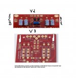
Cascode Q7-Q8 Orientation.
Take a look at the picture and see if I have my mind right, or if there was," A failure to communicate!"
I have attached the pin-outs to both chips.
Q8=2SA1837
Q7=2SC4739
https://www.mouser.com/ds/2/408/toshiba_2SA1837-1209454.pdf
https://www.mouser.com/ds/2/408/toshiba_2SC4793-1209408.pdf
Take a look at the picture and see if I have my mind right, or if there was," A failure to communicate!"
I have attached the pin-outs to both chips.
Q8=2SA1837
Q7=2SC4739
https://www.mouser.com/ds/2/408/toshiba_2SA1837-1209454.pdf
https://www.mouser.com/ds/2/408/toshiba_2SC4793-1209408.pdf
Attachments
Last edited:
Both devices are BCE
In both sides of the circuit the emitters connect to the Jfets. Look at the traces from the cascode transistors to the Jfets, luckily in this case they are on top and easy to see. Make sure the cascodes are oriented to connect emitter to Jfet. Which on this board will orientate the case back to the outside, I.E., as the silk is drawn.
Q7 is the N channel, Q8 is the P channel.
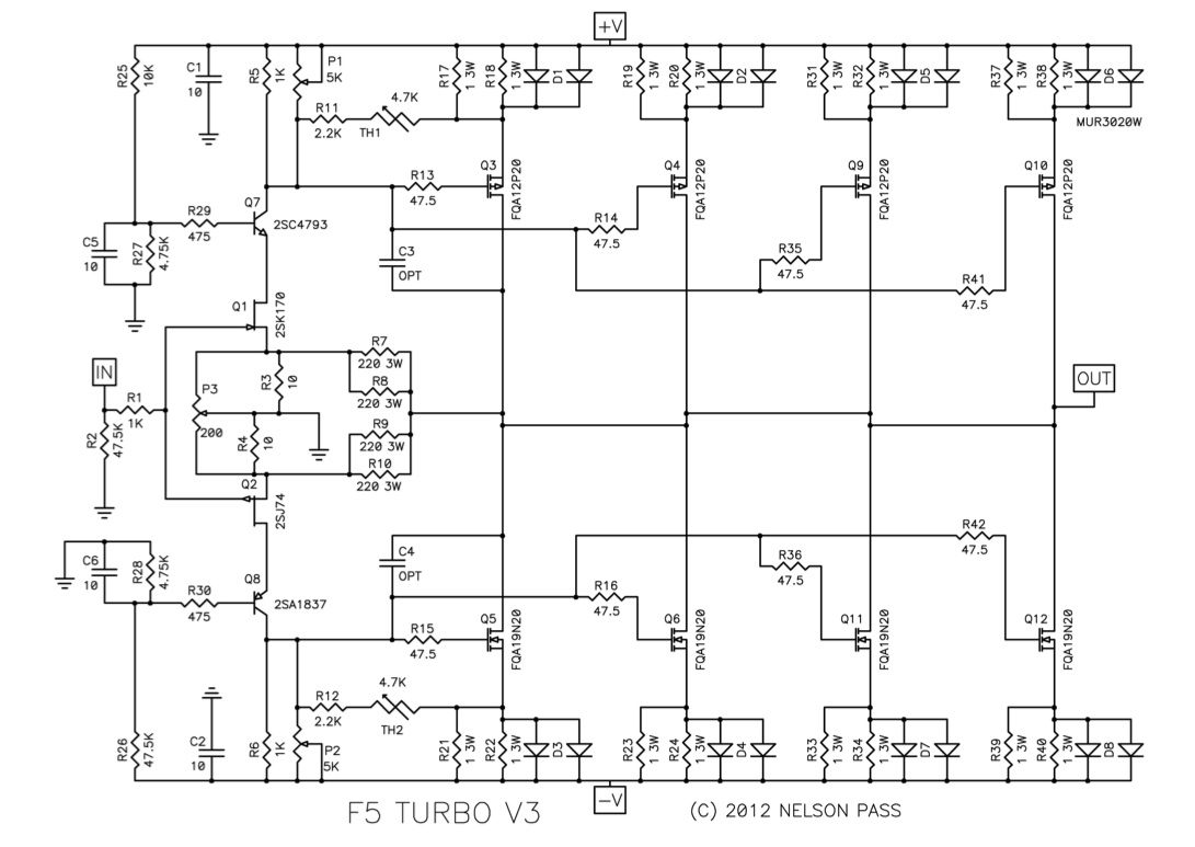
6L6,
Thanks, must have been late cause I swear it was backwards... sorry for the dense question. Go ahead and delete those two off there if ya like, don't see them helping anyone and just making the thread longer.
Thanks, must have been late cause I swear it was backwards... sorry for the dense question. Go ahead and delete those two off there if ya like, don't see them helping anyone and just making the thread longer.
F5T V2 Done
Thanks for the guide 6, and all who chimed in with advice, she runs great, since it's a Christmas present for a friend, I biased it at .3 firmly in the, scared kitty zone. I think it looks pretty good for a first time build.
Anyway, here's a little amp porn for ya.
Thanks for the guide 6, and all who chimed in with advice, she runs great, since it's a Christmas present for a friend, I biased it at .3 firmly in the, scared kitty zone. I think it looks pretty good for a first time build.
Anyway, here's a little amp porn for ya.
Attachments

- Home
- Amplifiers
- Pass Labs
- F5Turbo Illustrated Build Guide