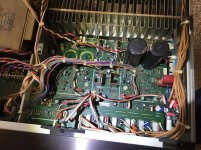
Hello, Trying to repair the left channel on this Sony ES amp and not having much luck. Suppose to be getting 45 vdc +- on the left side but only getting around 32vdc +-, also getting around 5 vdc on the speaker +-outputs of that channel which isn't good and causing speaker to pop. Any help on this would be greatly appreciated.
Thanks
Thanks
Sounds like an even worse problem than mine! Does it have transistor outputs or an ic? If it's transistors then check for shorts between the pins.
If you mean +/-45Vdc on the powerrails, the ServMan indicates +/-59Vdc.
Both channels are on the same supply, so on the right are the same railvoltages.
If only +/-45Vdc is reached and (+)5Vdc on the output, a serious shorting (Q417/Q419 - Q467/Q469) is causing both this wrong settings and the popping (better not connect speakers until repaired).
ServMan is on the HFengine.
If you mean +/-45Vdc on the powerrails, the ServMan indicates +/-59Vdc.
Both channels are on the same supply, so on the right are the same railvoltages.
If only +/-45Vdc is reached and (+)5Vdc on the output, a serious shorting (Q417/Q419 - Q467/Q469) is causing both this wrong settings and the popping (better not connect speakers until repaired).
ServMan is on the HFengine.
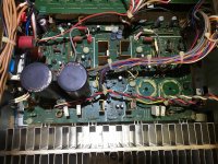
I'm sorry, I meant 50 vdc +- on power rails. No shorts on Sanken Transistors but on left channel I am getting 10k resistance on the E legs of those transistors 2SA1216 and 2SC2922 with the big caps removed on left channel. The caps had been leaking so I removed them to order replacements and cleaned up the board where the electrolytes had leaked. Not sure if it should have that 10k resistance to chassis ground on E legs left channel only?
Attachments

I got the 45 vdc +- from the transformer inputs test points and they tested a little low as well. If I remember correctly I was getting 42.3 vdc on the positive test point and 43.8 vdc on - TP.
Also Marsbravo I think you may be looking at the wrong schematics as there is no (Q417/Q419 - Q467/Q469) transistors on this amp. maybe you are looking at the Sony TA-F444ES(X) schematics?? This unit is only an ES model not ESX.
Also Marsbravo I think you may be looking at the wrong schematics as there is no (Q417/Q419 - Q467/Q469) transistors on this amp. maybe you are looking at the Sony TA-F444ES(X) schematics?? This unit is only an ES model not ESX.
A completely different amp from another sonyteam. One x, one century...
OK, tone control on separate pcb... wwwwrrrrruuuhhhh. Check check check connections. How on earth did that (no proper word) stroke in their heads.
I guess it is not or hardly possible to eschange powerrails from left and right? It might point to a power fail (caps) or an amp fail (Q314-Q315 / Q364-Q365).
The rest is straightforward, except this very odd 'current substractor (Q316 / Q366) circuit' in the front, possibly to switch off the inputdiff at power off.
I've known Sony as a thouroughly design manufacturer, but divergences from succesfull paths however may occur in various designs. Tone control in the feedback of the main amp, and switches included, on a separate pcb...
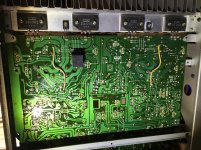
Amp has separate transformers for power amp unregulated supply.
Nominally +/-48Vdc. The candidates are,
transformer winding
noise path caps eg, C601, C915
rectifier bridge
main filter caps
Check/measure AC voltage on transformer secondary, compare with
other channel/transformer. Getting +/-32Vdc suggests cap failure/leaking
unlikely. Try measuring AC voltage on same voltage rails, long shot that
rectifier is breaking down
...long shot that rectifier is breaking down
True indeed and so simple. If underrated, it is a swift fix!
Titel of topic: Sony TA-F444ESX
We'll start over, no worries mate!
I've a look on it...
Man, I am so glad you pointed that out, I feel like a real dufus now! I copied and pasted the Sony model number and never noticed the X on the end. Can the title be edited still? Ughh. I am really sorry about that MarsBravo. Please excuse my stupidity.

Amp has separate transformers for power amp unregulated supply.
Nominally +/-48Vdc. The candidates are,
transformer winding
noise path caps eg, C601, C915
rectifier bridge
main filter caps
Check/measure AC voltage on transformer secondary, compare with
other channel/transformer. Getting +/-32Vdc suggests cap failure/leaking
unlikely. Try measuring AC voltage on same voltage rails, long shot that
rectifier is breaking down
Thanks mbz, I will check those things out and see what I can find. I screwed up on the title and its really a Sony TA-F444ES not ESX and only has 1 transformer instead of separate transformer for each channel.
It does have one transformer, but with three separate windigs: left, right and low voltage.
So if possible, check the bridge as said by mbz and if ok swap the rail wires left-right.
So if possible, check the bridge as said by mbz and if ok swap the rail wires left-right.
It does have one transformer, but with three separate windigs: left, right and low voltage.
So if possible, check the bridge as said by mbz and if ok swap the rail wires left-right.
Well Good news, Found a bad 2watt 2.2ohm resistor on volume right channel control board that was bad and reinstalled main rail caps on left channel and now I am getting 50 vdc +- at test points. I adjusted DC bias and DC idle on both channels and came out really close to spec within .1mv.
So then I hooked it up to test with speakers and barely turn volume and right channel jumps from no sound to full blast and have no adjustment. Left channel I get nothing but a little background hiss. So I think amp board is working but have a problem in volume board or pre amp?
Last edited:
Condensing into humble bad connections/solderings/interconnects of about everything crackling-connected to each other until broken and limb.
Any reference to this 2E2/2W res? Might point or clue to other to check issues.
Cheerio,
Any reference to this 2E2/2W res? Might point or clue to other to check issues.
Cheerio,
Condensing into humble bad connections/solderings/interconnects of about everything crackling-connected to each other until broken and limb.
Any reference to this 2E2/2W res? Might point or clue to other to check issues.
Cheerio,
Only had a 5 Watt resistor to replace it with. would it be possible that it took out one of the ne5532p on the right channel?
Attachments
![IMG_0933[1].jpg](/community/data/attachments/714/714642-f299da514683d11b466fc6ade3106df7.jpg?hash=8pnaUUaD0R)
Condensing into humble bad connections/solderings/interconnects of about everything crackling-connected to each other until broken and limb.
Any reference to this 2E2/2W res? Might point or clue to other to check issues.
Cheerio,
Only had a 5 Watt resistor to replace it with. would it be possible that it took out one of the ne5532p on the right channel? I am getting the 15vdc +- to the volume board. not sure how to test opamp?
I have to look into detail on this, currently falling in pieces right now... tbcont.
Okay, I removed preamp (Volume) board and removed and tested opamps. One of the NE5532p's are bad for sure but the opamp in front of the 2 NE5532p's is an NEC C4082C and it doesnt test same as the NE5532p's so I cant tell if it is good or bad. Would you know of any good replacements for it? I have a bunch of audio opamp stock like TL072, LM358, OP275, AD797az, OPA2164, OPA2134, AD823, AD712, OPA2228 etc...
Thanks!
- Home
- Amplifiers
- Solid State
- Need help left ch. dc voltage on Sony TA-F444ESX