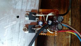
Built this circuit with 30-0-30 supply, driving a 17.5 ohm center tapped load. Scoped from center tap of the load to output of primary amplifier has very nice output, but the other inverted amplifier output is lacking resolution and decreased power. I do have some TL-072 chips that I could possibly employ to resolve the asymmetry issue, but would rather put those to use in a high power solid state amp. Any suggestions from knowledgable experts frequenting this forum shedding some light on what measures can be taken to resolve this issue are greatly appreciated.
Thanks, and happy DIYing! 🙂
Thanks, and happy DIYing! 🙂
Attachments
Last edited:
Try scoping each output with GND (0v) as the reference
I assume you left the center tap floating?
I assume you left the center tap floating?
Last edited:
Shorting c7 yeilds no change in the output waveform whatsoever. Now I wonder why it is even called for in the schematic...
And yes ubergeeknz, that centertap is left unconnected to ground or anything other than the probe reference.
And yes ubergeeknz, that centertap is left unconnected to ground or anything other than the probe reference.
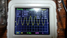
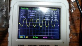
Just tried scoping the outputs (still loaded BTL mode 17.5 ohms) and the primary chip output was clipping, so I reduced the input signal until a perfect sine was achieved. The output on the second chip still very diminished by comparison. (51v p-p vs 21v p-p)
->CORRECTION! I just noticed that the INPUT SIDE AMPLIFIER is actually the one with diminished power, NOT the inverted one!
Perhaps I should also mention that my load is actually 2 transformers in series. I plan to drive 4 power transistors in BTL mode with the output of these 2 transformers.
The sine looks good when referencing to gnd, but the inverted amp output is lacking power, and scopes out as pictured above when referenced to the tapped center between the 2 trafos.
Last edited:
Could be that the problem is caused by the centre-tapped load? Try it with a 16 Ohm resistor between the outputs.
Pokeing around with my probe I am seeing a very pretty sine of 17.64v p-p!!! on pin 2 of the inverting amplifier that I initially thought was the one with diminished power. Maybe there is too much power at the inverting amplifier that is crippling the primary chip? I will keep at it and see what I can see...
Using a varistor I connected between pin 2 and GND on the primary amplifier, as I reduced resistance to GND, the output increased quite rapidly. The output also increased a tiny bit on the inverted amplifier as well. Looks like I just need to set this circuit up on a breadboard and tinker with values until I find a happy balance for the 2 LM1875 chips. Thanks for any tips, and please, keep 'em coming! I ain't done yet! 🙂
Using a varistor I connected between pin 2 and GND on the primary amplifier, as I reduced resistance to GND, the output increased quite rapidly. The output also increased a tiny bit on the inverted amplifier as well. Looks like I just need to set this circuit up on a breadboard and tinker with values until I find a happy balance for the 2 LM1875 chips. Thanks for any tips, and please, keep 'em coming! I ain't done yet! 🙂
Last edited:
Check R8Pokeing around with my probe I am seeing a very pretty sine of 17.64v p-p!!! on pin 2 of the inverting amplifier that I initially thought was the one with diminished power. Maybe there is too much power at the inverting amplifier that is crippling the primary chip? I will keep at it and see what I can see...
Spot on ubergeeknz! when I was connecting all the ground leads looks like I missed that one. I am not seeing 17v sine on pin 2 now, registering zero on both pin 1&2 on the inverting amplifier. Output is symmetrical. My transformers are not. I guess there are differing materials in the ferrite cores I used because I am still seeing a difference in waveform and power on those transformers. If reverse the arrangement the problem follows the arrangement. Oh well guess I get to build a new set of identical transformers. Thanks for the help! \m/
Not quite sure why you want to drive power transistors off the transformers still. What do you want to achieve?
Also worth noting, transformers "reflect" impedance. So with nothing on the secondaries of those transformers, you may get strange results. Try putting the expected load on the secondaries so that the impedance is reflected on the primaries.
Honestly, I have not had any luck building a discrete power amplifier as of yet, at least I learned enough to check hfe for matching transistors for LTP but no actual working circuit as of yet. I suppose I got lucky with the first transformer coupled attempt getting a pretty darn good sounding 100 watt amp from 30-0-30 supply. I am hoping to quadruple that number but my transformers have to be right on the money to get those power transistors to deliver. Stumbled on issues with impedence reflection through transformers so that is why I am using 2 seperate, identical transformers tying their primaries together in series and using lm1875 drivers in BTL mode to get the voltage swing as high as possible. A 5:1 ratio on the transformers brings the voltage and current into range to drive the power transistors in common emitter mode class AB arrangement for what I hope to be somewhere in the range of 300 - 500 watts.
I have breadboarded the digi125 and aksa-55 but did not work. I am learning though. No problem setting up working simulations in LTSpice, shouldn't be long before I start having some success with the discrete amps. Anyway, thanks again for sharing.
I have breadboarded the digi125 and aksa-55 but did not work. I am learning though. No problem setting up working simulations in LTSpice, shouldn't be long before I start having some success with the discrete amps. Anyway, thanks again for sharing.
A very interesting approach... Will be pretty cool to see what you come up with. Have fun with your project.
C2 and C7 are an order of magnitude too small, so at LF there will be asymmetry due to mismatched electrolytics and the LF roll off starts too soon.
R4 and R6 seem suspiciously small. 100nF / 10 ohms are by far the commonest Zobel network used and for good reason.
R4 and R6 seem suspiciously small. 100nF / 10 ohms are by far the commonest Zobel network used and for good reason.
- Home
- Amplifiers
- Chip Amps
- bridged LM1875 >>ASYMMETRY<< issue