Well,you talk about 'decades ago'. You talk about repairing equipment that is obsolete: VCR's, CD and DVD players.
I don't know what you 'don't buy', but 10's of 1000's of people are buying those active speakers with build in SMPS. In an era where a single returned unit on warranty can wipe out the profit of 200 sold units, it seems your view isn't corresponding to the real world.
Things change.
Jan
Jan, it's obvious that you sound biased with this SMPS thing.
And that's fully your own business and pleasure.
Those VCR's and such were not "obsolete" when they were needing repair to their SMPS, so I fail to understand your comment about them.
Some I had to repair while still under warranty!
As for the "10's of 1000's" of people purchasing "new" speakers, they don't have a clue as to what's inside the box, or how it was designed.
But if they knew, they might step carefully.
Old Uncle George and Granny Martha don't know crap about SMPS, and why should they?
On the websites that only professional techs use (needing a valid licensed service tech application for membership) I've seen plenty of chatter about defective products both old and recent.
Us professional techs also discuss the issues and workarounds, as well as the manufacturer's important service bulletins regarding "changes" to be made for such things.
This information is of course something that you cannot readily aquire, but trust me, it's all there.
Switch mode power supplies rely on the ability of inductors to transform magnetic energy to any voltage. To achieve this, an inductor is energised with a pulse of current until its core reaches a predefined flux density. Then, current is very quickly swiched off, which forces the inductor to deliver that energy through a fast rectifier diode to charge an electrolytic capacitor. The rate of magnetic field collapse determines the voltage supplied by the inductor. To achieve this, a triangle wave oscillator, a comparator and an error amplifier are used. The error amplifier amplifies the difference between the output voltage and a multiple of a fixed reference voltage. The error is fed to the comparator with the other input fed from the output of the triangle wave generator. With the correct polarities, the pulse width from the comparator increases with increasing error voltage from the error amplifier. This feeds more energy into the inductor during the energising stage. The inductor has to deliver all its energy to the output capacitor so that it would not saturate causing the swiching mosfet to short circuit during the energising phase.
The above, is only one type of switching power supply, the flyback converter. There is also the forward converter which works differently. As a reader may notice, switching power supplies rely heavily on switching times, which means, transistor turn on and turn off times have to be scrupolously considered. Since diodes in the output circuit do not instantly respond to when the inductor starts feeding them current, there is a high voltage spike and ringing in the inductor. This RF travels in weird ways causing difficult to block interference. The heavy current spikes rectified in the output diodes also generate RF exacerbating the problem. The problem of ringing is so real, that switching power supplies often employ snubber circuits to quickly damp ringing. High voltage spikes in switching transformers are generated due to collapsing leakage flux which is not linked with secondary coils. As soon as a switching mosfet turns off, this leakage flux collapses very quickly causing high voltage ringing.
As if these issues are not enough, the fact that a switching power supply uses a square wave of a high frequency, (>= 100kHz by very conservative standards) the harmonics necessarily fall into RF. This RF can flow through difficult to identify current paths.
I conclude by writing that back in 1992 I built a switching power supply based on the chip L296. This power supply still works and sometimes was used day and night non-stop. During those times, I was a young adult, and was literally fascinated by the way switching power supplies achieve voltage regulation at an extremely high efficiency. In my young mind, the ability of an inductor to dynamically supply a range of voltages was like a beautiful cult.
Last edited:
"Don't judge the words, look at the actions". Professional stuff is all about SMPS these days, so whatever their flaws, they don't break down left and right.
30 years ago it was different. I remember the first SONY class D amp with SMPS (TA-N88) routinely needed a new SMPS. But that was 1974 or thereabouts.
And there is nothing inherently unreliable in an SMPS, it's a bunch of Rs, Cs, diodes, Xformers, ICs, what have you, processing volts and currents, and it is straight-forward engineering to design it such that it is reliable for its purpose.
You can't take the situation of 30 years ago and conclude SMPS is crap. It isn't, and they are here to stay, and those clunky xformer-based supplies will slowly fade away except in some nooks and crannies populated by nostalgic diy-ers. 😎
Jan
As if these issues are not enough, the fact that a switching power supply uses a square wave of a high frequency, (>= 100kHz by very conservative standards) the harmonics necessarily fall into RF. This RF can flow through difficult to identify current paths.
This just isn't true. My SilentSwitchers switch at 1.2MHz* and the C and L parts are so small, and the PCB layout so good (he said, modestly) that the result is quieter than anything but a Superreg-class linear regulator.
You guys all keep hanging in old times, as if a square wave is by definition something bad, as if anything switching is by definition radiating more than the junk we get through a mains transformer when the neighbor switches on his LED lighting. We've got something better now, through an advanced concept called 'electronic engineering'.
Jan
* your 100kHz is 30 years old btw, you got to keep up!
Last edited:
Jan, you are talking about secondary side converters, off-line converters are a different story. Over the years I designed a bunch of primary side converters and can say that most of actual designs operate well below 75kHz: Thus the second harmonic is kept below 150kHz making them easier em-compliant.* your 100kHz is 30 years old btw, you got to keep up!
For my knowledge offline-converters operating in the 1Mhz ballpark have been designed since 1~2 decades but are targeting the >1kw high power server market.
Last edited:
Seems like Jan is steadfast in his beliefs and opinions of SMPS supplies, and nobody is going to tell him differently.
But to conclude that some others are "nostalgic DIY'ers" because of different beliefs is going a bit far out.
But to conclude that some others are "nostalgic DIY'ers" because of different beliefs is going a bit far out.
Come on guys, my problem isn’t a 10,000watts amplifier it’s just a little smps with less than 16pcs of component not even bigger or complex like my iPad charger.
I’m literally just begging for 3-4amps of power (I already have the voltages under control) there must be an pwm ic that uses few parts whether internal or external mosfet that you can recommend on a schematic (I’ll take my chances I have a lot of these boxes so I will get it right).
This was the design I modified to the circuit to drive the smps transformer, however the transformer has two primary winding unlike one in the schematic.
Attachments
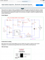
Some points about the posted SMPS schematic:
i) The mains voltage is halve wave rectified
ii) The high voltage switching transistor is integrated in the IC
iii) The switching transformer is of the flyback type
iv) The IC is supplied power through an electrolytic capacitor used as a voltage dropper.
In such a design, current output is limited by the current handling capacity of the flyback transformer and switching power transistor. The transformer has the highest bearing on this current limitation.
How it works:
Energy is stored in the transformer core as a magnetic field. The magnitic field intensity might almost reach the core's saturation magnetic field. Trying to magnetise the core beyond this saturation, results in its magnetic field failing to rise with magnetising current preventing the primary from setting up a back emf. This situation, leads to the switching transistor having to handle all the supply voltage resulting in a short circuit transistor condition. This is catastrophic for the switching transistor.
To increase the current output in any flyback SMPS, you will have to change the switching frequency and the turns number on the primary coil and secondary coil. This can be achieved by calculating the new higher operating frequency and changing the frequency determining capacitor if it is an external component.
One tempting but apparently simple way is to use full wave mains rectification instead of the existing halve wave rectification. You can also add a smoothing capacitor to the rectified mains. This will, however, force you to use a resistance voltage dropper instead of a capacitive dropper for the IC. This should, in theory, double the power.
Note and Warning:
I do not know whether the chip will like full wave rectification instead of halve wave rectification. You will have to understand the datasheet that comes with this chip. This chip seems to be designed for SMSP power factor correction which expects a rectified sinusoidal input voltage.
Last edited:
One tempting but apparently simple way is to use full wave mains rectification instead of the existing halve wave rectification. You can also add a smoothing capacitor to the rectified mains. This will, however, force you to use a resistance voltage dropper instead of a capacitive dropper for the IC. This should, in theory, double the power.
Could you practically make the edits on the schematic I post and repost it back, the transformer that I have tho is 2pairs primary windings.
If you search for the chip datasheet you will find a circuit using it employing full rectification of the mains. The problem with this circuit is the fact it uses a very high voltage. Rectified mains is 330V DC in Europe and around 160V DC in the US. An error or omission, can easily result in circuit destruction. This is why I am suggesting you to consult the chip datasheet as published by the manufacturer. You have also to make sure the power supply works as intended before powering anything with it you are not comfortable to destroy. Besides this, such a power supply requires a current limiter during the testing phase. You can use a low power (10W) mains filament bulb. Do not use higher ratings as this is a low power circuit. As a load you can use a wirewound resistor or a low voltage light bulb.
I beg your pardon if this post disappoints you, but high voltage has no mercy on components. Furthermore, the forum rules bind respondents to warn readers when high voltage is used. Testing this circuit after adding a full rectifier bridge, a smoothing reservoir capacitor for the rectified mains, and a dropper resistor for the chip, has to be planned and done carefully to avoid destruction of the circuit and injury to yourself.
A simpler and more secure way, is to find a replacement SMPS power supply which delivers the DC power and voltage you require.
Last edited:
Hi Formas,
I get the impression that the flow of suggestions how to modify the old SMPS has reduced heavily.
You still wish to modify the “old” SMPS?
As already suggested by Osvaldo, the TOPxxx from Power Integrations are interesting candidates. A single IC, looking like an LM1875 (TO-220) but with 6 pins that can deliver well above 100W at the output of a transformer. The TOP260 can deliver more than 100W with the right transformer.
TI shows in 1st page of their TNY268 datasheet ( https://www.power.com/sites/default/files/product-docs/tny263_268.pdf ) the power levels this IC can deliver. 10-20W with the right transfomer. The old SMPS transformer is not optimized for the TNY268 and it would never be possible to get the 75W you need.
The max. output power depends on the max. current the power switch can handle and the switching frequency. The TOP260 exists in versions that should allow both 66KHz or 132KHz switching. The old SMPS probably ran closer to 66KHz than 132KHz. You say you have one that still functions and delivers +/-13.6V. Could you please measure the switching frequency on that one?
If you decide to try with the TOP260, you still need to draw-up the circuit of the old SMPS so we know what we are modifying. The second primary winding you mention could be an auxiliary winding for supplying the IC after start-up.
The max. output power depends on the max. current the power switch can handle and the switching frequency.
It also depends in the transformer design (In fact, coupled inductors in Fly Back and Quasi Resonant topologies), because the core area and wire section defines the temperature rise, and the gap, the max voltages and DC through the windings,
Last edited:
I’m converting to linear, smps didn’t turn out well on the forum.
I’m at 12v center tap transformer with 3amp, I’ve wired up it plays loud, but it’s swinging from between 11ish and 13ish on idle it’s at 15ish, my question are as follows:
Why is it still cutting out when driven volume hard, I’m still losing amperage. **(it’s way better than previous with the smps tho)
Should I just add the secondary transformer wires where the smps secondary was removed?
Should I remove the two diodes and add an full bridge rectifier?
Should I upgrade 25/1000uf to 25/2200uf?
Should I use a 12v (pos) regulator for the usb/card reader circuit.
What can be done to make it stablish?
Attachments
Hi Formas,
With an ordinary transformer and full-rectification using a bridge-rectifier, the power line decoupling capacitors are recharged by the transformer every 10ms. In-between the recharging, the current for the amplifier is taken from the decoupling capacitors.
A 10000uF capacitor will in 10ms loose 1V of its voltage when loaded with 1A.
With 60Hz net frequency, it is slightly better but not much.
In your case when you turn up the volume, let's assume you pull a current of 1A. With only 1000uF, the capacitor will lose 10V in 10ms. If the capacitor was recharged to 16V for a start, it will fall well below 10V toward the end of the 10ms period. You have an enormous voltage ripple when you turn up the volume. That shows when you measure an "11ish" voltage with your voltmeter (slow).
Further, it seems you are using only two diodes thus single rectification. Then, the period in-between recharge becomes 20ms and the voltage drop the double!
You need to use the 12V center tap trafo with a bridge rectifier and at least 10000uF for each voltage rail before it will start function well.
You can leave the 1000uF that are already there. If you have decided for a traditional transformer supply, you better remove the two diodes such that the old SMPS power supply circuit is disconnected from the amplifier. The outputs from the new 10000uF (or more) capacitors are connected directly to the 1000uF capacitors. Be careful using the correct polarity.
Last edited:
Hi Formas,
With an ordinary transformer and full-rectification using a bridge-rectifier, the power line decoupling capacitors are recharged by the transformer every 10ms. In-between the recharging, the current for the amplifier is taken from the decoupling capacitors.
A 10000uF capacitor will in 10ms loose 1V of its voltage when loaded with 1A.
With 60Hz net frequency, it is slightly better but not much.
In your case when you turn up the volume, let's assume you pull a current of 1A. With only 1000uF, the capacitor will lose 10V in 10ms. If the capacitor was recharged to 16V for a start, it will fall well below 10V toward the end of the 10ms period. You have an enormous voltage ripple when you turn up the volume. That shows when you measure an "11ish" voltage with your voltmeter (slow).
Further, it seems you are using only two diodes thus single rectification. Then, the period in-between recharge becomes 20ms and the voltage drop the double!
You need to use the 12V center tap trafo with a bridge rectifier and at least 10000uF for each voltage rail before it will start function well.
You can leave the 1000uF that are already there. If you have decided for a traditional transformer supply, you better remove the two diodes such that the old SMPS power supply circuit is disconnected from the amplifier. The outputs from the new 10000uF (or more) capacitors are connected directly to the 1000uF capacitors. Be careful using the correct polarity.
FF

Good, solid advice and decision .. and bets are that your customers will be the happier for it.
Sure is an interesting problem, though -- how many of these naughty little guys are you stuck with, anyway?
And I should confess, I'm more than a little OCD -- now that I've worked most of the way through the TNY268 data sheet, a decent bit of the LTV-8x7 sheets, and every last post in this thread (aagh!), and hacked through the small storm of misunderstandings and unintended insults, I feel ready to tackle what I THINK was your original request -- 'what parts [that are available this side of the Pacific Ocean] could replace the smoked originals, giving the same performance and (hopefully) better reliability?'
I can tell you with certainty that the TNY263-268 series parts won't do it. You'll need a controller IC and separate MOSFET. But the pinout of the original IC is unfamiliar to me -- 7/8 pin options are common enough, but the ones I've encountered don't employ a separate output device. The pinout of the MOSFET is common enough, and with some time we may be able to find a pin-compatible replacement for the controller IC, but you'd probably need more than 10 or 15 of these failed bad boys to warrant the effort. We'll need full specs or an examplar of the transformer to start with -- and that's the point at which we start duplicating the work the original designer did (or should have).
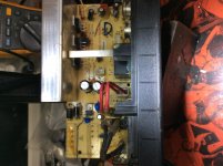
Couple things to note about the TNY263/68 series parts: Their data sheet says they top-out at 23 Watts (output). And, just about any 7/8-pin IC that handles line juice - and has multiple pins devoted to 'Hot negative'(usually MOSFET Source), will need ALL OF THEM connected to a large copper plane for heat sinking. The 'Dead Bug' style shown in one of your pictures won't work; connect ALL of the Source pins to a decent copper plane for heat sinking. If you don't, chances are that the IC will impose thermal [current] limiting well before you reach the desired output power.
I may be too slow to help you with this situation, but I am willing ...
On the other hand, if you (and your customers) are completely happy with the linear replacement PSU, I'm OK with that, too.
-Rick
Sure is an interesting problem, though -- how many of these naughty little guys are you stuck with, anyway?
And I should confess, I'm more than a little OCD -- now that I've worked most of the way through the TNY268 data sheet, a decent bit of the LTV-8x7 sheets, and every last post in this thread (aagh!), and hacked through the small storm of misunderstandings and unintended insults, I feel ready to tackle what I THINK was your original request -- 'what parts [that are available this side of the Pacific Ocean] could replace the smoked originals, giving the same performance and (hopefully) better reliability?'
I can tell you with certainty that the TNY263-268 series parts won't do it. You'll need a controller IC and separate MOSFET. But the pinout of the original IC is unfamiliar to me -- 7/8 pin options are common enough, but the ones I've encountered don't employ a separate output device. The pinout of the MOSFET is common enough, and with some time we may be able to find a pin-compatible replacement for the controller IC, but you'd probably need more than 10 or 15 of these failed bad boys to warrant the effort. We'll need full specs or an examplar of the transformer to start with -- and that's the point at which we start duplicating the work the original designer did (or should have).
Couple things to note about the TNY263/68 series parts: Their data sheet says they top-out at 23 Watts (output). And, just about any 7/8-pin IC that handles line juice - and has multiple pins devoted to 'Hot negative'(usually MOSFET Source), will need ALL OF THEM connected to a large copper plane for heat sinking. The 'Dead Bug' style shown in one of your pictures won't work; connect ALL of the Source pins to a decent copper plane for heat sinking. If you don't, chances are that the IC will impose thermal [current] limiting well before you reach the desired output power.
I may be too slow to help you with this situation, but I am willing ...
On the other hand, if you (and your customers) are completely happy with the linear replacement PSU, I'm OK with that, too.
-Rick
Last edited:
Seems like Jan is steadfast in his beliefs and opinions of SMPS supplies, and nobody is going to tell him differently.
But to conclude that some others are "nostalgic DIY'ers" because of different beliefs is going a bit far out.
There is nothing to tell differently. Jan knows switch mode supplies, you don't.
May I say you sound the exact same, without being impolite? 😀Seems like Jan is steadfast in his beliefs and opinions of SMPS supplies, and nobody is going to tell him differently.
Can we mention the pot calling the kettle black? 😛
Maybe your user name choice slightly hints at that, WISEOLD Tech?But to conclude that some others are "nostalgic DIY'ers" because of different beliefs is going a bit far out.

 😀
😀Seriously:
1) SMPS have come a long way.
2) **ALL** supplies eventually fail.
Of course we see here the bad ones so failures are over represented.
Only difference is that being way more complex and still not standardized by any means (meaning they are not mature technology by any means, they change all the time) people find them harder to repair, while, well, a transformer, 4 diodes and 2 capacitors are simpler and faster to troubleshoot.
That said, we still get cries for help on these every day.
In my opinion, SMPS are by far much better than standard linear ones. Think for example, what a power supply will needed for a standard PC if they must be done with common materials, say, BJT's as series regulators, 50Hz trafos, big can caps, etc.
SMPS's generally destroys itself preventing damages to their loads, and from this inherent safety they have price.
I designed and repaired several of them including DC/DC converters, and are a largely interesting item.
SMPS's generally destroys itself preventing damages to their loads, and from this inherent safety they have price.
I designed and repaired several of them including DC/DC converters, and are a largely interesting item.
- Home
- Amplifiers
- Power Supplies
- How to increase amperage in SMPS circuit?