I was reading this Emission Labs article and wondered if anyone has experience to share with this noval way of connecting the DHT filament.
Rod, if you might be reading this, would it be appropriate to connect your heater supply to the center of these new tubes?
Rod, if you might be reading this, would it be appropriate to connect your heater supply to the center of these new tubes?
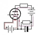
Hi Jaap, Yes, you can connect my Filament Regulator across the «normal» terminals of the EML V4 series centre-tapped DHTs. Connect the centre-tap to ground via the cathode resistor, if used.
The noise-rejection capability of the centre-tap is not needed if you use my regulator though - the noise is in the µA region already, and the usual reason for choosing the centre-tap does not have such benefits.
The noise-rejection capability of the centre-tap is not needed if you use my regulator though - the noise is in the µA region already, and the usual reason for choosing the centre-tap does not have such benefits.

The center tap can be used for a better partition of the anode current over the cathode (heaters).
I don't believe it can. The 'partition' is the distribution of current across the emissive surface.
This is forced by the 5V bias-skew of the filament voltage.
With the centre-tap in place, you can change the partition between the filament terminals - but that does not make any serious change to the distribution across the emissive surface.
The ends of the filament are connected by ~3.5Ω (hot-resistance of the filament substrate -Tungsten in case of EML). The current-distribution remains determined by the bias, regardless of which pin the anode-current emerges (enters) from.
Electrons always go from minus to positive, also in the heater wire.On the way from -5V to +5V it loses electrons to the outside direction anode.All the electrons flowing away on the positive side have to come from the -5V end without tap.
By feeding electrons to the tap releaves the first part of the heater from conducting the hole Ia.
Without the tap the negatieve side of the heater gets more current and hotter.
Mona
By feeding electrons to the tap releaves the first part of the heater from conducting the hole Ia.
Without the tap the negatieve side of the heater gets more current and hotter.
Mona
Without the tap the negatieve side of the heater gets more current and hotter.
Mona
The positive side takes more of the current: V(grid-k) is lower = hotter bias.
Electrons always go from minus to positive, also in the heater wire.On the way from -5V to +5V it loses electrons to the outside direction anode.All the electrons flowing away on the positive side have to come from the -5V end without tap.
By feeding electrons to the tap releaves the first part of the heater from conducting the hole Ia.
Without the tap the negatieve side of the heater gets more current and hotter.
Mona
We can agree that the current in/out of the terminals can be changed. But the bias-voltage at every point along the filament is effectively the same, whether you have a centre-tap or not. It's the bias voltage that determines the current distribution from the oxide coating.
Electrons can't go in two directions in the same conductor at the same time. In the heater current flows from minus to positive.Those who leaves the cathode has to come from the negative side. With more emission on the positieve side (hotter bias) means more electrons pass through the negatieve side to get there. Result is the more you get to the positive side the less current flows.The positive side takes more of the current: V(grid-k) is lower = hotter bias.
The negatieve side starts with If+Ia and at the positive side is only If. With a resistor between minus and tap part of the bigger current is bridged and pass to the less current part.
Mona
Attachments
<cut>
With a resistor between minus and tap part of the bigger current is bridged and pass to the less current part.
Mona
The Negative side and the centre-tap are already bridged by the filament substrate - the non-emissive part of the filament. To be specific, for the EML DHTs half the filament amounts to about 1.8Ω while it is heated.
Given that low value resistance is already present across these two nodes, what value of external resistor are you proposing to apply, that will make any (substantial) difference?
You are worrying about the heating effect of the anode current in the actual substrate of the filament?Electrons always go from minus to positive, also in the heater wire.On the way from -5V to +5V it loses electrons to the outside direction anode.All the electrons flowing away on the positive side have to come from the -5V end without tap. By feeding electrons to the tap releaves the first part of the heater from conducting the hole Ia. Without the tap the negatieve side of the heater gets more current and hotter.
Putting some numbers in, based on EML 300B Uf=5V If1.35A; Ia=70mA
Effective hot resistance of the filament substrate is 3.7Ω
Power dissipation in HALF of the filament:
- Due to heating current: ca. 3.4W
- due to the whole anode current Ia: ca. 0.009W
There is no need to be concerned about this negligible power dissipation increase - even if you could change it.
With a heater current of 1200mA the difference of half the anode current 70/2mA between the two heater sections is only 3%, not very much indeed. The resistor i proposed was an answer to the question, what to do with a center tap, not to solve a real issue. Question what value for the resistor, suppose Ia=70mA, the rsistor is 5V/70mA=~70Ω
Mona
Mona
- Home
- Amplifiers
- Tubes / Valves
- SE triode with center tapped filament