If you are talking to me, it's just a cut from OD to ID. Not sure what my bandsaw does, maybe 25 mils. I'll measure tonight.Can you supply a drawing for the radial slit, pls
THx-RNMarsh
If you were talking to tvi.....then nevermind..😉
With luck, I will have at least the brass and aluminum done tonight for test tomorrow during lunch...twill be interesting to see how the calculated break frequencies correspond to onset of exclusion and dissipation.
jn
Nice metal work there jn!!
//
//
Thank you. I didn't have the B&W 700 whitepaper. The audioroundtable stuff, man, wayne parnham, a name from the past.
The Amhet paper I found about a week ago.
Again, thanks.
John
Edit..update on the winding mandrel and tweeter rings...
Made two side plates for the mandrel, slotted so they allow the mandrel to expand. The M3 screws are tightened after mandrel is sized. The fixture on the right was used to make the plates.
The second pic is an old blown tweet coil (my son), then brass, alum, and copper blank. Haven't purchased any magnetic steel yet.
yes, thx. Any eddy currents involved.... before or after slit cut?If you are talking to me, it's just a cut from OD to ID. Not sure what my bandsaw does, maybe 25 mils. I'll measure tonight.
in
https://physics.stackexchange.com/questions/199560/eddy-currents-tubes-with-slits
electromagnetism - Eddy currents Vs. Inducing EMF in opposing the change? - Physics Stack Exchange
?
THx-RNMarsh
Last edited:
“If you are talking to me, it's just a cut from OD to ID. Not sure what my bandsaw does, maybe 25 mils. I'll measure tonight.”
Scotty not clear to me jn. Do you mean a slit cut across the pole piece running through the centre?
Scotty not clear to me jn. Do you mean a slit cut across the pole piece running through the centre?
😀 That would be the least of my worries on personal info disclosure.The hell with privacy. We need your personal details so we can harass you!
Good one!drama queen i.e. pontificatory self-victimisation
How about "victim card fanatic"?

“If you are talking to me, it's just a cut from OD to ID. Not sure what my bandsaw does, maybe 25 mils. I'll measure tonight.”
Scotty not clear to me jn. Do you mean a slit cut across the pole piece running through the centre?
I think there's a pic @ POST #28706
tried to move the pic but can't seem to do it on my phone.
You take the pole plate, which is the steel plate that is on the other side of the flux gap from the pole piece. You split it from ID to OD the same way a lock washer (AKA split washer) is split.
You take the pole plate, which is the steel plate that is on the other side of the flux gap from the pole piece. You split it from ID to OD the same way a lock washer (AKA split washer) is split.
Bingo.
Jn
I think there's a pic @ POST #28706
tried to move the pic but can't seem to do it on my phone.
I didn't post a pic. But I can draw one up tomorrow, if I have time.
Both the alum and brass are ID and OD correct, but still too thick. I can't believe my bottle of super glue dried up..
 I have the facing mandrel made, but can't glue the rings in place to cut the thickness.
I"m still going to measure tomorrow bare, alum, and brass. But I'll still have to recalc the resistance for the thicker rings. If I can finish that during lunch, I'll be happy.
The copper is going slow...it's a square plate, and I can't hold it properly in a 3 jaw chuck. Which of course means, I need a 4 jaw.. Point and click with credit card, here I come..
I was pricing 2.75 inch diameter copper rod..holy mackerel, that stuff is expensive!! I need about 2 inches of that, and about 4 inches of 3 inch diameter magnetic steel.
Jn
Thanks. I have an advantage in that I have an absolutely excellent machinist I work with, he is a tremendous resource to answer all my really stupid questions. And there are a lot of those..Nice metal work there jn!!
//
Jn
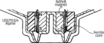
The Alpine patent uses other means to the same end see first pic.
closer to what you are doing
US5357587 Distortion reduction in loudspeakers
GRODINSKY ROBERT M; CORNWELL DAVID G
In FIG. 1B, which is a rear view of a loudspeaker magnetic structure, the paths of the AC signal induced eddy currents in bottom plate 12 and pole piece 13 are illustrated. For a given polarity of AC signal in voice coil 14, the dashed line 24 shows the direction of eddy current flow in pole piece 13. Dashed line 25 represents eddy current flow in bottom plate 12 that is electrically coupled from pole piece 13. For the same polarity AC signal, the eddy currents that traverse the outer paths illustrated by dashed lines 26 and 27 in bottom plate 12 rotate in a reverse direction from those illustrated by the dashed lines 24 and 25. The difference reflects the reversal that occurs as flux travelling up the pole piece changes direction as it returns through the top plate 11, the magnet 10 and the bottom plate 12 as shown in FIG. 1A. Because the voice coil 14 surrounds the pole piece 13, the AC flux and the resulting eddy currents are highly concentrated. In the prior art, the pole piece is both electrically and magnetically connected to the bottom plate, which allows the concentrated eddy currents to couple into the bottom plate where they oppose and partially cancel the reverse rotating eddy currents induced by the returning flux. The result is distortion in the form of smear due to the phase differences between eddy currents in the top plate 11, which is not electrically connected to the pole piece, and eddy currents in the bottom plate, which is electrically connected to the pole piece. The resultant electrical fields from these eddy currents in both top and bottom plates induce rotating dielectric currents in the magnet, which adds distortion.
In FIG. 3, a more complex pole piece structure is illustrated. This structure further reduces eddy current distortion with an insulated pole extension 48, which also helps to linearize the magnetic flux in the vicinity of the voice coil and to reduce variations in the voice coil inductance. In this version, the bottom plate 42 is in contact with the second pole piece section 45 which is insulated from first pole piece section 43 by thin insulating washer 46. Another thin insulating washer 47 insulates pole extension 48 from first pole piece section 43. Slots 41 and 49 are formed in first pole piece section 43 and pole extension 48, respectively, for further reducing distortion by altering the eddy current flow patterns to reduce the coupling of the energy therein to other magnetic circuit elements. The slots also increase the eddy current path lengths which increases the resistance of these paths.
-------------------------------
have a few more...
Attachments
😀 That would be the least of my worries on personal info disclosure.
Good one!
How about "victim card fanatic"?
😀
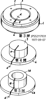
@In the aforementioned conventional speaker, the ring-shaped iron plate 73 and the iron yoke 77 are used as component parts of the magnetic circuit. Therefore, the magnetic field of the voice coil 76 produced by applying voice current (alternating current) thereto develops eddy currents in the ring-shaped plate 73 and the yoke 77 which define the magnetic gap 79. These eddy currents are the primary cause of sound distortion.
"The very low inductance of the voice coil 76 increases to a high value when it is placed close to the ring-shaped iron plate 73 and the iron yoke 77. Therefore, the impedance increases from the intermediate-frequency to high-frequency ranges, which leads to reduced sound conversion efficiency. At the same time, phase rotation increases due to impedance, which causes a distortion in the output sound phase."
I might be jumping the gun, but is this perhaps an explanation as to why current drive lowers distortion?
@tvi so the slit is just down thee side of the pole piece per the drawing?
I might be jumping the gun,
IMO they exaggerate. For their case, they should provide measurements for the three effects
These eddy currents are the primary cause of sound distortion.
Therefore, the impedance increases from the intermediate-frequency to high-frequency ranges, which leads to reduced sound conversion efficiency.
At the same time, phase rotation increases due to impedance, which causes a distortion in the output sound phase."
I hope JN will provide measurements before and after slitting the pole and front plate (in a dedicated thread)
George
Thanks again, great stuff.
But nobody slits the front plate. I would have thought that the front plate as a shorted turn would have been obvious.
Jn
I was thinking... If I had some spare D-205TI drivers, I would just take the diaphragm assembly out of the magnet structure, put the assembly on the bandsaw, and cut from the edge to the center of the pole piece. That would eliminate the need for insulating the front plate from the magnet and would cut down the pole piece and magnet shorted turn currents.
Cleaning the gap would not be too easy, but certainly doable.
Then, use some JB weld to fill in the kerf all the way around. That way, dust can't get into the gap.
Unfortunately, I have 6 of these puppies in service, no spare magent structures, and only two replacement diaphragms, one of which I am using for this test.
jn
Seems I mentioned this as a question #28866 with no response.The Alpine patent uses other means to the same end see first pic.
The resultant electrical fields from these eddy currents in both top and bottom plates induce rotating dielectric currents in the magnet, which adds distortion.
The slots also increase the eddy current path lengths which increases the resistance of these paths.
-------------------------------
have a few more...
"yes, thx. Any eddy currents involved.... before or after slit cut?"
What affect would it have?
THx-RNMarsh
In other words, increased impedance from the cut(s) will reduce the effectiveness of the "short".
No? Yes? Maybe?
THx-RNMarsh
Then, use some JB weld to fill in the kerf all the way around. That way, dust can't get into the gap.
Unfortunately, I have 6 of these puppies in service, no spare magent structures, and only two replacement diaphragms, one of which I am using for this test.
jn
JB weld uses iron filings as a reinforcement, so maybe choose a different epoxy. 🙂
JB weld uses iron filings as a reinforcement, so maybe choose a different epoxy. 🙂
I'll check a tube at home with a magnet, I thought it was non magnetic as well as non conductive.
John
JB weld makes a few different compositions under their brand, but their "classic" dark grey stuff is both conductive and magnetic from the filings. Not extremely so, but enough to matter when you need something truly non-conductive/non-magnetic. It's bitten me before on some prototypes at work, where I grabbed the tubes out of convenience. For most things, it's a great product.
JB weld makes a few different compositions under their brand, but their "classic" dark grey stuff is both conductive and magnetic from the filings.
I've used golf shafting epoxy filled with 220 SiC abrasive grit. Indestructible stuff.
First pass shorting rings on D205TI 2 inch diameter selenium tweeter replacement diaphragm.
The brass is .300 inches thick, aluminum is .250 inches thick.
Both are 2.05 inch ID, both are 2.6 OD.
I'll repeat when I have turned them to .100 inch.
Note: the inductance number at 100 hz is wonky, there is something going on with the meter. I suspect calibration, and will try an agilent soon enough. edit: ah, I'm not doing a shorted zerocal, so the measure at LF is going to be questionable when the reactance is small.
As I had mentioned previously, the aspect ratio of a voice coil plays a very large role in these measurements, as a much higher percentage of the coil is very close to the shorting ring. As a result, inductance very quickly takes a hit. Resistance still takes up to 2Khz before it begins to increase. Above 50Khz, I do not like the data, something nefarious is happening, not necessarily due to the components.
It will be interesting to see what happens when the ring has permeability orders of magnitude higher than free air.
jn
Edit: had to redo the post, I accidentally had millihenries instead of microhenries...
Attachments

Last edited:
- Status
- Not open for further replies.
- Home
- Member Areas
- The Lounge
- John Curl's Blowtorch preamplifier part III