Does anyone have experience with STEG amplifiers. the amplifier has blinking red and green LEDS which indicates amplifier is muting status caused by overheating output short-circuit or output too low impedance load.
protect pin has = 5v
grd/fault = 0.079v
pwm/fan = 0.004v
mute = 0.004v
should mute be at 5v or grd/fault be at 5v
grd/fault = 0.079v
pwm/fan = 0.004v
mute = 0.004v
should mute be at 5v or grd/fault be at 5v
I apologize I read the manual wrong. turns out amp is muting status caused by improper GND ground connections.
that the exact model. I downloaded the k2.02 version amplifier model. this is how I got as far as I did. the components dont have a thorough amount of labeling. I am going to have to pull the whole board to find the problem
Try connecting a 47R 1w resistor in parallel with a 100n cap between secondary ground and battery ground.that the exact model. I downloaded the k2.02 version amplifier model. this is how I got as far as I did. the components dont have a thorough amount of labeling. I am going to have to pull the whole board to find the problem
hey perry is the suggestion by Mario a shunt resistor to ground? or Mario please explain the reasoning behind this
These ones are hell of ride when they fail...
If i'm being correct all of the k* steg series amps are dsp/microprocessed managed...
If i'm being correct all of the k* steg series amps are dsp/microprocessed managed...
Sorry, for my absence, I was on vacation.hey perry is the suggestion by Mario a shunt resistor to ground? or Mario please explain the reasoning behind this
K series STEG amplifiers are engineered amplifiers in Italy, for a very long period they were also produced in Italy, then, for cost reasons, the production was moved to China.
They are all managed by a microprocessor which, however, manages only the protections, while the PWM of the power supply and the audio are managed as a very common class AB or D.
For this reason, if there is a problem, this is communicated to the processor which eventually blocks the power supply PWM and communicates the error by flashing the LEDs.
If you take a look at the amplifier user manual, you can find the type of problem by referring to the type of flashing of the LEDs.
Usually your type of problem derives from a ground virtual problem, for this reason the addition of a resistor with a value between 33 and 100R between primary and secondary mass could solve the problem.
In the past it has already happened to me and I solved it this way.
Sorry, for my absence, I was on vacation.
K series STEG amplifiers are engineered amplifiers in Italy, for a very long period they were also produced in Italy, then, for cost reasons, the production was moved to China.
They are all managed by a microprocessor which, however, manages only the protections, while the PWM of the power supply and the audio are managed as a very common class AB or D.
For this reason, if there is a problem, this is communicated to the processor which eventually blocks the power supply PWM and communicates the error by flashing the LEDs.
If you take a look at the amplifier user manual, you can find the type of problem by referring to the type of flashing of the LEDs.
Usually your type of problem derives from a ground virtual problem, for this reason the addition of a resistor with a value between 33 and 100R between primary and secondary ground could solve the problem.
In the past it has already happened to me and I solved it this way.
He knows more about these amps than I do.
The primary and secondary for many amps are connected with a 1k resistor (value varies) in parallel with a capacitor so this wouldn't be a radical idea.
The problem can sometimes be caused by a signal source that doesn't have a shield with a connection to the amplifier ground.
The primary and secondary for many amps are connected with a 1k resistor (value varies) in parallel with a capacitor so this wouldn't be a radical idea.
The problem can sometimes be caused by a signal source that doesn't have a shield with a connection to the amplifier ground.
is there a specific place that I would add this addition to the amplifier? is there already on of these installed and just needs to be increased in value resistance.
can you make a couple of photos?is there a specific place that I would add this addition to the amplifier? is there already on of these installed and just needs to be increased in value resistance.
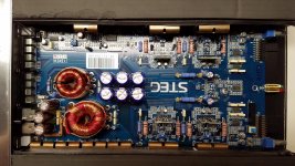
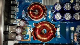
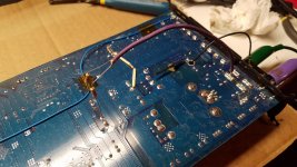
here are the pics requested.
Attachments

I'm not sure if I understand but if an amp has positive and negative rail voltage, the negative terminal of one bank of rail caps will be at the negative rail voltage. Don't power it up if you have one 330 ohm resistor connected to the negative rail.
Wait for the other forum member who made the suggestion to clarify what you are supposed to do.
Wait for the other forum member who made the suggestion to clarify what you are supposed to do.
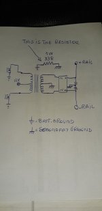
You did not understand.I have installed a 33ohm resistor on both sets of rail caps (negative) and attached it to ground. please advise if this is correct. both red and green LEDs are still flashing.
The resistor should be installed from the center point of those capacitors to the battery ground.
You installed them from + rail and - rail to the battery ground.
Thus you will get a great SHORT CIRCUIT.
Attachments
- Home
- General Interest
- Car Audio
- STEG K4.01