You can certainly test this very nice cap in this very poor line stage.Hello!
thank you for your answer. the only reason to change is that I have a pair
of Mundorf Silver Oil 0,56 for test here!
Maybe i let it better by 0,47uf!
Best regards!
It can only drive high input impedance power amps with either valve or fet inputs and offers no real advantage to a passive preamp. For most applications gain is also excessive.
Chinese origins?
With high impedence tube circuits, I don't understand the reasoning for using such high capacitance values for coupling.
It effects response speed in some cases by loading down signal/level changes, and having an amplifier with ability down to sub-sonic levels is deterimental to performance as well.
Who really needs to listen/have soundwaves at 10 hz in their music anyway?
It only causes woofer "flopping" and increases rumble and hum effects.
And that makes what you hear as music sound crappy.
Well... there are effects on transient response and phase to consider when one sets a cut-off frequency. You were referring to blocking with "response speed"?
Basically the Time Constant concerning capacitors themselves. Dependent on the associated components and impedences. And overly big capacitance in a high impedence circuit will perform "sloppy", thick, sluggish, particularly with high frequencies.Well... there are effects on transient response and phase to consider when one sets a cut-off frequency. You were referring to blocking with "response speed"?
If I understand you correctly, you mean to say that in the audio band propagation delay can be heared. So, if I connect a tonegenerator through -lets say a 10K- resistor to my two channel oscilloscope, one channel coupled by double the capacitance as the other, the signals will be shifted?
If I understand you correctly, you mean to say that in the audio band propagation delay can be heared. So, if I connect a tonegenerator through -lets say a 10K- resistor to my two channel oscilloscope, one channel coupled by double the capacitance as the other, the signals will be shifted?
No. You have to understand what Time Constants are about, with capacitors vs impedance.
You see, a lot of gear is engineered with over-sized coupling capacitors, why? - I believe to impress, or extract frequencies below human hearing. That does nothing for performance, and actually harms things at the upper end of the frequency scale. A big high mfd cap will obviously take longer to charge/discharge/reverse the AC signal for a given signal level and particular impedance. I certainly don't want my equipment to act "sluggish" or blurred in the high frequency department. And I don't need subsonic frequencies producing rumble or power-robbing woofer-pumping over things that aren't hearable.
Not Chinese, it is the Audio Note L2 ...
Same thing, just more expensive parts 😛
Sorry, not an AN fan. I would expect the Mundorf to be too strikingly different to the AN polyesters for the change to be entirely positive.
Well, I might understand it once visualised. Can you come up with a practical tonegenerator and oscilloscope example?
I certainly don't want my equipment to act "sluggish" or blurred in the high frequency department.
This may be a good subjective description of how big caps sound but none of this can be confirmed by measurements. And you don't really need to constantly discharge coupling caps, so the time constant is pretty much irrelevant. Not arguing with your observations, just your explanations.
Despite the extended LF bandwidth a dc connection brings none of the blurring of a coupling cap, so imho limiting the bandwidth is not the answer.
Perhaps this is a valid point to consider? it's not the same AC signal passing the coupling capacitor. With a small value the HPF cuts the lowest frequencies while producing a phase shift in low tones, changing the dynamics. A high value passes all, subjectively putting high frequencie details to the background.
Using expensive components in a poor design is even more pointless than using expensive components in a good design.
Using expensive components in a poor design is even more pointless than using expensive components in a good design.
Wait…
it just occurred to me, that perhaps it is exactly for the shortcoming of the design, that the hobbyist is attempting to improve it … with a fancy-schmancy part, highly touted for its effortless breath and soundstage presence (chuckles allowed).
Right?
GoatGuy ✓
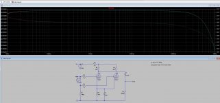
Just for interest, I threw a schematic together in LTspice and ran an AC sweep (hopefully correct). I used the .step command to see the effect of the two stated values.

As expected, there is little difference except right at the very bottom end:
(Close up of the audio range)

As expected, there is little difference except right at the very bottom end:
(Close up of the audio range)
Attachments

avtech₂₃;5906008 said:Just for interest, I threw a schematic together in LTspice and ran an AC sweep (hopefully correct). I used the .step command to see the effect of the two stated values.
Coolio… 2 things:
Note a subtle mistake … not connecting the pair of 12AU7 triodes anodes together. Per the original schematic on page 1.
Second, note on the right hand vertical scale legend (in the “closeup”), that the difference at 10 Hz is only 0.04 dB. Not something humans can hear. The most golden ears, with even paced music playback (i.e. not sine waves) can't tell the difference of even 1 dB, let along 0.04 of them.
ratio = 10dB/20
ratio = 100.04 ÷ 20
ratio = 1.0046
So, about ½% difference. At 10 Hz. Which we don't hear anyway. ratio = 100.04 ÷ 20
ratio = 1.0046
Thank you tho' for the sim.
I appreciate simming: tho' it makes it easy to see response curves, I am always a wee bit suspicious of the internal accuracy of the valve-model used in simulation. Real life results tend to differ.
Just saying,
GoatGuy ✓
Coolio… 2 things:
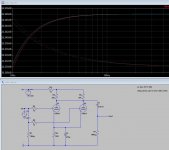
Note a subtle mistake … not connecting the pair of 12AU7 triodes anodes together. Per the original schematic on page 1.
Whoops.. good spot, I missed the join when I ran the wires.
Not much change:
Second, note on the right hand vertical scale legend (in the “closeup”), that the difference at 10 Hz is only 0.04 dB. Not something humans can hear. The most golden ears, with even paced music playback (i.e. not sine waves) can't tell the difference of even 1 dB, let along 0.04 of them.ratio = 10dB/20So, about ½% difference. At 10 Hz. Which we don't hear anyway.
ratio = 100.04 ÷ 20
ratio = 1.0046
Thank you tho' for the sim.
Thanks for the Math! It helps my understanding when I see worked examples like that.
Attachments
avtech₂₃;5906109 said:Whoops.. good spot, I missed the join ... Thanks for the Math! It helps my understanding when I see worked examples like that.
You are welcome, fellow DIYer. Note that even I, the goatish math guy, made a mistake too. It wasn't –0.04 dB at 10 Hz, but –0.003 dB. Even less to worry about in the wee hours of the morning. Nice work. GoatGuy ✓
- Status
- Not open for further replies.
- Home
- Amplifiers
- Tubes / Valves
- changing the value of coupling capacitor