Hi everybody!
I want to buil a power supply for amplifier and I want to use the famous
schematic from Dejan Veselinovic in TNT-Audio site.
I have ONLY one toroidal (Talema) with ONLY one dual-output, 25-0, 25-0
that is exactly the needed for this schematic.
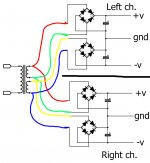
The problem is that I wish to use ONE schematic for each channel,to minimize crosstalk so,
is it possible to make something as in photo?
Sorry for the horryble design, I hope it is clean enough....
I know the ideal is another toroidal but it is much expensive (the one I have
I buyed used....)
Sorry for my bad english, I don't use google...
Thanks for helping me....
I want to buil a power supply for amplifier and I want to use the famous
schematic from Dejan Veselinovic in TNT-Audio site.
I have ONLY one toroidal (Talema) with ONLY one dual-output, 25-0, 25-0
that is exactly the needed for this schematic.
The problem is that I wish to use ONE schematic for each channel,to minimize crosstalk so,
is it possible to make something as in photo?
Sorry for the horryble design, I hope it is clean enough....
I know the ideal is another toroidal but it is much expensive (the one I have
I buyed used....)
Sorry for my bad english, I don't use google...
Thanks for helping me....
Attachments
Last edited:
Almost guaranteed to have a problem with hum caused by the current returning via the ground loop. It can work if you use one bride per amp so that you can connect the grounds before the amps as would be the case with a center tap.
Almost guaranteed to have a problem with hum caused by the current returning via the ground loop. It can work if you use one bride per amp so that you can connect the grounds before the amps as would be the case with a center tap.
Really????😕
and so.....what to do?
One bridge per amp/channel and use center tap for ground instead of the (frankly, weird) dual bridge arrangement.Really????😕
and so.....what to do?
Almost guaranteed to have a problem with hum caused by the current returning via the ground loop. It can work if you use one bride per amp so that you can connect the grounds before the amps as would be the case with a center tap.
Where's the ground loop?
I don't see how linking to the confusion in that thread helps without an explanation of what you mean. Sorry Mark, were you replying to ubergeeknz?
Last edited:
Ah, I see. I wonder though, is this dual bridge arrangement actually better than one bridge with CT? It seems to introduce additional voltage drop and impedance due to there being more diodes in the path?I was but you are right about that thread.
It's doubtful there's any advantage, I've heard it suggested the fact it keeps ground currents out of the transformer may be one?
This discussion grows very difficult to me...
I think I must abandon my idea.
For the original schematic, NOT the one I posted, do you think is good to use for each channel?
I think I must abandon my idea.
For the original schematic, NOT the one I posted, do you think is good to use for each channel?
I too cannot seem to find good reasoning or evidence for it... Seems like a case of more must be better.It's doubtful there's any advantage, I've heard it suggested the fact it keeps ground currents out of the transformer may be one?
This discussion grows very difficult to me...
I think I must abandon my idea.
For the original schematic, NOT the one I posted, do you think is good to use for each channel?
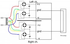
I use two bridges with two secondaries to make one power supply that I use for both channels. I don't think there is any need to abandon your idea.
I use two bridges with two secondaries to make one power supply that I use for both channels. I don't think there is any need to abandon your idea.
ok, I understand...
so I use original schematic from Dejan, powering both channel.
- Home
- Amplifiers
- Power Supplies
- A PSU with 4 bridge