That's what I would do, I don't think crosstalk is an issue, but I also don't think there is anything wrong with your idea. Try it, experimenting is half the fun of DIY and it would be simple enough to change it if there is a problem 🙂ok, I understand...
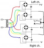
so I use original schematic from Dejan, powering both channel.
There is a general rule in electronics, which is often omitted from textbooks because writers think it is too obvious to state yet many newbies remain ignorant of this rule. The rule is:
Two things cannot be both isolated and connected.
If you use one pair of secondaries to feed two PSUs feeding two amps then the two amps are connected via the secondaries and the ground. If you want isolation then you need two sets of secondaries or two transformers.
Two things cannot be both isolated and connected.
If you use one pair of secondaries to feed two PSUs feeding two amps then the two amps are connected via the secondaries and the ground. If you want isolation then you need two sets of secondaries or two transformers.
In ideal world, it should work (but bring no benefit): the voltage drops in the diodes and wires of the two channels would be identical, making the two channels power GND's equipotential.
This means that no balancing current will flow dowstream, in the load section where both GND's will be united.
This also means that a single ground should be able to do exactly the same job.
But this also means that if the dynamic diode drops and voltages induced along the wires are not strictly identical, balancing current will exist downstream, creating ground currents.
With some luck, it won't be too noticeable, but it will generally cause an unpleasant buzz. More = better?
Multiple bridges like this waste more power to forward voltage in the diodes, and introduce more components that could fail, all at extra cost. I don't see the advantage, just extra cost and complexity and lower efficiency.
More = better?
I refer to the seemingly common belief that if something is more complicated, and costs more to make, it must be better.
I'm more in the simple and proven camp. But variety is the spice of life!
If it were me, I'd build it with a single set of DC rails and one bridge first, and see how it performs. If not happy (ie. With the channel seperation) try splitting it out and see if it makes a difference. At least this way you're less likely to introduce new and interesting problems.
Good point, I think he should try it and report back 🙂But this also means that if the dynamic diode drops and voltages induced along the wires are not strictly identical, balancing current will exist downstream, creating ground currents.
With the proposed arrangement of two PSUs fed from the same secondaries, the best that can be achieved is the same as you could get from one PSU feeding the two amp channels. If you are unlucky it will be worse than this.
Simplest option is one bridge feeding a pair of caps.
Simplest option is one bridge feeding a pair of caps.
There is still a ground loop - just not in a place where it will cause hum. And those connections from the star ground back to the individual supply center taps add impedance in series with the reservoir caps, reducing their effectiveness at high frequency. This arrangement will likely require more local decoupling on the amp boards than would otherwise be required. The simplest solution is often the best.
Indeed, but unlike direct paralleling (to increase current rating f.e.), the scheme will also bring weird, wonderful and unpredictable effects like buzzing: an audiophile delight, because there infinite possibilities and tweaks to alter the buzz and "improve" the sound.
What could be better?
What could be better?
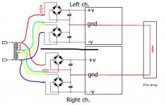
the attached grounding method works, with no hum.
Yes, that is better. Still no channel isolation, so no better than using just one PSU to power both channels.
No ground isolation but that was always impossible sharing the same set of secondaries.Yes, that is better. Still no channel isolation, so no better than using just one PSU to power both channels.
There is at least a degree of decoupling between channels.
Hey.
I hope this thread is a good place to ask the question:
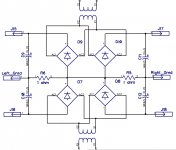
Will this circuit work?
As in: not generate cross channel hum, AND, not blow up due to shorting the secondaries?
The challenge (from a different "amplifier" thread) is as follows:
Four diode bridges, but only two secondary windings.
Stereo amplifier.
Will this circuit resolve the cross channel hum problem (assuming a common ground for both channels on the source of the signal), or only make it worse?
Two Hum Breaking Resistors ('HBR'), each of 1 ohms, for the "Left_Ground" and the "Right_Ground".
The charge currents flowing through the HBR resistors essentially compensate themselves and null out, as I believe, due to the differential nature of the charge currents for the positive rail and the negative rail, passing same resistor and nulling out. So that these resistors seem not increase the impedance of the PSU, as visible from the perspective of the left/right amplifier boards (I hope).
I suppose that this could be simulated in LT Spice, some way or another.
But then, these resistors also serve the double purpose of being HBR resistors, essentially separating the left/right ground. Any hum voltage, arising from the cross-channel ground loop, will drop out on these resistors, and they are outside of the signal paths.
Will this work?
Is there a flaw in here somewhere, like diodes shorting the secondaries, and I do not see it?
...
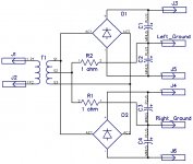
The second drawing shows a similar concept, but using just two bridges. Will it work and kill hum?
Am I shorting the secondaries via diodes somewhere? I do not see it.
The general assumption here is that we have two secondary windings, providing the same AC voltage value.
Windings may, or may not, have exactly the same internal DC resistance.
Critique and comments - kindly welcome.
I hope this thread is a good place to ask the question:
Will this circuit work?
As in: not generate cross channel hum, AND, not blow up due to shorting the secondaries?
The challenge (from a different "amplifier" thread) is as follows:
Four diode bridges, but only two secondary windings.
Stereo amplifier.
Will this circuit resolve the cross channel hum problem (assuming a common ground for both channels on the source of the signal), or only make it worse?
Two Hum Breaking Resistors ('HBR'), each of 1 ohms, for the "Left_Ground" and the "Right_Ground".
The charge currents flowing through the HBR resistors essentially compensate themselves and null out, as I believe, due to the differential nature of the charge currents for the positive rail and the negative rail, passing same resistor and nulling out. So that these resistors seem not increase the impedance of the PSU, as visible from the perspective of the left/right amplifier boards (I hope).
I suppose that this could be simulated in LT Spice, some way or another.
But then, these resistors also serve the double purpose of being HBR resistors, essentially separating the left/right ground. Any hum voltage, arising from the cross-channel ground loop, will drop out on these resistors, and they are outside of the signal paths.
Will this work?
Is there a flaw in here somewhere, like diodes shorting the secondaries, and I do not see it?
...
The second drawing shows a similar concept, but using just two bridges. Will it work and kill hum?
Am I shorting the secondaries via diodes somewhere? I do not see it.
The general assumption here is that we have two secondary windings, providing the same AC voltage value.
Windings may, or may not, have exactly the same internal DC resistance.
Critique and comments - kindly welcome.
Attachments
Last edited:
You've added resistance into the speaker return circuit unnecessarily. Better to have the HBR in the usual place.
Please show me, where did I add it.You've added resistance into the speaker return circuit unnecessarily. Better to have the HBR in the usual place.
I do not see it.
There is no current flowing through these resistors (caveat: equal voltage secondaries and equal current draw from positive/negative rails by the amplifier boards).
The net differential current flowing through each of them is zero.
There are two speaker returns: the "Left_Ground" and the "Right_Ground".
These resistors are not in the ground returns of the two Speaker Circuits. I hope / pray / believe. Possibly - I might be in error. But what if I am not?
Last edited:
At what point in the AC signal cycle do the positive and negative parts of the amplifier draw exactly equal current? At what point do they not draw equal current? Which one dominates?
If you have two signal grounds (left and right) is there any point in the signal chain where these might need to be connected together? If you connect them what currents might flow, given that in the PSU they are separate and so might adopt different potentials?
If you have two signal grounds (left and right) is there any point in the signal chain where these might need to be connected together? If you connect them what currents might flow, given that in the PSU they are separate and so might adopt different potentials?
>>>> At what point in the AC signal cycle do the positive and negative parts of the amplifier draw exactly equal current?
In a non-perfect World - scarce and far between, in a short term, single cycle perspective. But in a longer term, multiple-cycles perspective, things hopefully tend to "even out" on the huge PSU filter capacitors, which, as I see it, are acting as a huge integrator, i.e. an energy tank that the amplifier sees, as its source of current supply, during normal operations. PSU capacitors deal with ripple. So they will deal with this particular ripple also.
>>>> At what point do they not draw equal current? Which one dominates?
I'm not sure ... In class B that would be an annoying sequence: top rail - bottom rail - top ... - bottom ... - interchanging. According to the music content, where the zero-crossings of the signal would determine which is which.
Class AB would tend to look a bit nicer.
Class A - possibly - very nice.
But then again, even in class B or AB, across a time span of more than one cycle, I would hope (in vain? or reasonable assumption?) that they would tend to even out, due to the huge time constant of the main filter caps, which stand between these resistors and the rest of amp.
>>> If you have two signal grounds (left and right) is there any point in the signal chain where these might need to be connected together?
Yes, indeed. They would be connected.
And they will create a loop.
I am not trying to fight the loop or get rid of it.
I am trying to make it unsubstantial.
The Left_Ground and Right_Ground will almost certainly "meet" at the common analog ground of the DAC, or other signal source. So, yes, we do have a ground loop. But (hopefully) a harmless one. Harmless, because the 1 ohm hum breaker resistors are on the "other side" of the PSU capacitors. They are not in the signal path.
And yes, the Left_Ground "sees" the Right_Ground, via the two series connected resistors, totaling 2 ohms.
And it is these very resistors that most of the hum drops out on, and not for example on the screen of the RCA interconnects, which have a magnitude lesser series resistance, and hence a magnitude lesser hum generating effect.
In other words: we loose almost all the hum at the point of the ground loops highest resistance, i.e. on the two 1+1 ohm resistors, which are not in any signal path.
Hopefully.
>>>>If you connect them what currents might flow, given that in the PSU they are separate and so might adopt different potentials?
A ground loop is basically a ... circle. A loop. And, as in any other electrical circuit, it can be modeled as a voltage source (the hum as intercepted by the loop) and a series connection of following resistors.
In our case: four resistors:
1). Screen of RCA interconnect of the left channel (say, 20 miliohms), +
2). Screen of RCA interconnect of the right channel (say, 20 miliohms), +
3). Hum Breaker resistor in my proposed circuit (Right_Ground: 1 ohm) +
4). Hum Breaker resistor in my proposed circuit (Left_Ground: 1 ohm)
According to the voltage divider rule, we have the hum from the voltage source splitting on our voltage divider in following proportion:
V_actual_hum = V_max_hum * (20+20) / (1000+1000+20+20).
V_actual_hum = V_max_hum * 40 / 2040 = V_max_hum * 0,0196
This means that the actual hum as "generated" on the screens of the RCA interconnects is now only 1,96% of what it was without implementing such a concept.
In decibels, that would be 20 log ( 0,0196 ) = -34 dB,
meaning a 34 dB improvement in terms of S/N in comparison to the "alternative" traditional scenario.
If 34 dB seems a tad thin, we could try to increase the value of these 1 ohm resistors. Maybe 2.2 ohms? Maybe 3.3? 4.7? This would need to be simulated and or tested. Walking on unknown territory here. New stuff.
At least for me.
This method does not exclude any other known and popular methods that are used as a remedy to cross-channel hum, such as keeping the interconnects close together to each other, etc.
If my rambling about the proposed schematic does not make much sense, then please fire away and tell me where I am in error here. Open to criticism, open to new knowledge.
Last edited:
- Home
- Amplifiers
- Power Supplies
- A PSU with 4 bridge