Hello guys,
I would like to ask if a 5k Output transformer be a good choice instead of the 3 to 3.5k that is specified on the schematic? I really would like to get some thoughts about this.
DIY Audio Projects Forum • Information
Here is the schematic with actual measurements from a builder.
Thanks
I would like to ask if a 5k Output transformer be a good choice instead of the 3 to 3.5k that is specified on the schematic? I really would like to get some thoughts about this.
DIY Audio Projects Forum • Information
Here is the schematic with actual measurements from a builder.
Thanks
Attachments
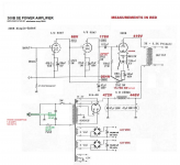
I wonder about the DC voltage reading at pin 4 of the 300B. 4.9VDC, really? The 300B is cathode biased, so it should be somewhere around +80VDC to ground from the 300B cathode.
Transformers can do a good job of matching a 300B to a resistive load. Speakers have impedances that vary.
Take a 5k to 8 Ohm transformer. Load the transformer's 8 Ohm tap with an 8 Ohm loudspeaker that is 6 Ohms minimum. The 5k transformer presents 3750 Ohms to the 300B.
Take a lossless 5k transformer: (lossless core, Primary DCR = 0, Secondary DCR = 0, and perfect winding coupling). A 300B with plate resistance, rp of 700 Ohms gives a damping factor of 7.14. Gain: u x (RL/(RL + rp)) 3.85 (5000/5700) = 3.38 The damping factor will be less, there is loss in the transformer. Gain x grid bias gives the maximum plate swing (if current, load impedance, and B+ permit).
Take a lossless 3k transformer: (lossless core, Primary DCR = 0, Secondary DCR = 0, and perfect winding coupling). A 300B with plate resistance, rp of 700 Ohms gives a damping factor of 4.29. Gain: u x (RL/(RL + rp)) 3.85 (3000/3700) = 3.12 The damping factor will be less, there is loss in the transformer. Gain x grid bias gives the maximum plate swing (if current, load impedance, and B+ permit).
Power out will depend on B+, primary impedance, grid bias, plate dissipation of the quiescent current and plate voltage.
Generally: Distortion with 5000 Ohm RL can be lower than with 3000 Ohms RL, but the power will be less with 5000 Ohm RL.
There are too many variables to know all factors, unless you know the quiescent operating conditions of the 300B (just like Eli Duttman said). The link he gave looks like it might be a rip-off of Western Electric's 300B chart. Search for the Western Electric 300B chart, it includes the 3rd harmonic distortion too; very interesting.
Last edited:
There are too many variables to know all factors, unless you know the quiescent operating conditions of the 300B (just like Eli Duttman said). The link he gave looks like it might be a rip-off of Western Electric's 300B chart.
AFAIK, it is the WE chart. WE is said to have sold 300Bs in the UK under the STC "mark" as 4300Bs. The link I previously provided is the 2nd in a set of 3. The 1st gif is here.
Here is the old data WE 300B sheet. It includes the 3rd harmonic numbers.
It also has the traditional set of curves to put a load line on.
https://www.westernelectric.com/static/library/specifications/tubes/300B.pdf
It also has the traditional set of curves to put a load line on.
https://www.westernelectric.com/static/library/specifications/tubes/300B.pdf
There's no reason why you can't , especially if you already have the output transformers. But understand that you'll get less power out than with a lower primary impedance at the same operating point.
More info with graphs showing distortion as a function of load resistance .
Click the specifications tab Here.
So the closer the specs of the tube you are using are to those of the Western Electric the more accurate the data sheet will be for you.
More info with graphs showing distortion as a function of load resistance .
Click the specifications tab Here.
So the closer the specs of the tube you are using are to those of the Western Electric the more accurate the data sheet will be for you.
Attachments
I have used the traditional plate curves that are in my post #7 link, to design Single Ended 300B amps with both 5K and 3K output transformers.
Think about the damping factor your speakers might need. Think about the power your speakers might need. Think about the distortion you want at a specific power. Think about how hard you want to run the 300B. At 300V and 60mA, the plate dissipation is only 18Watts. At 40Watts plate dissipation, it will be real hot, and may not last as long. There is already 6 Watts heat from the filament. 46W in a small lamp enclosure. They are all a tradeoff.
Those 5K and 3K transformers I used were for 300B tubes. But I used the same transformers for 2A3 (3K and 5K) and for 45 (5K). Each of those amps had its own good sound within its particular power range. Talk about a transformer that was loafing . . . the 5K with the 45 tubes 36mA current. No saturation at low frequencies.
I recommend using DC for the filaments; some others will disagree.
Have fun building, and some great listening too.
Last edited:
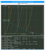
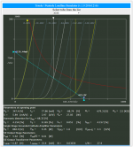
WE 300B data (at Up = 350 V) shows that using 5k OPT instead of 3k will reduce power from 8.3 W to 6.2 W, which is 1.3 dB. At the same time THD will drop some 5 dB. To me 5 k seems better choice.
Yes, but only clean DC. Just a rectifier and a large cap is not clean. Plenty of threads on which are good solutions for that.I recommend using DC for the filaments; some others will disagree.
As far as distortion goes for a 300B SE amp that does not have negative feedback, The linear range of power will have mostly 2nd Harmonic distortion, and the 3rd harmonic will be quite a bit lower.
2nd harmonic is merely the octave above the fundamental, and most consider that it does not sound bad. (if you reverse your speaker leads, the 2nd harmonic of the speaker will either partially cancel with the 2nd harmonic of the amp, or it will increase the total 2nd harmonic. 2nd harmonic distortion that is in phase adds, but out of phase cancels (similar to push pull).
3rd harmonic is considered by many to sound worse than 2nd harmonic. So when you pick an operating voltage, current, and load resistance for the 300B, consider that. But of course, know your loudspeaker impedance(s) versus frequency, and consider that too.
I have used regulated DC filaments in one SE DHT amp.
I used AC filaments on one 45 SE stereo amp, no room or filament current for any other way (did not like that). Other SE DHT used AC filaments, and I did not like that. I used a spectrum analyzer to look at the 120Hz sidebands on each and every music note from the AC filaments on those SE DHT amps.
After that, I used brute force CRC filter for DC filaments on SE DHT. I had 1mV to 2 mV ripple, which was low enough to keep those 120Hz sidebands below the noise.
Don’t forget that as the 300B plate current goes up, the plate resistance goes down. So when you pick the plate voltage and current, you need to also consider the output transformer impedance (a higher load impedance gives a higher damping factor).
The other design factor is the driver that is needed to deliver 2x the 300B bias voltage. If the 300B bias is -90V, you need +/- 90V from the driver. If the 300B bias is -45V, you need +/- 45V from the driver. etc.
why notHello guys,
I would like to ask if a 5k Output transformer be a good choice instead of the 3 to 3.5k that is specified on the schematic? I really would like to get some thoughts about this.
DIY Audio Projects Forum • Information
Here is the schematic with actual measurements from a builder.
Thanks
 i like distortion profile
Attachments
Hi Guys,
I thank you all for the response and I very much appreciate it. It is just the kind of response i needed.
===
Hi 6a3,
Whats your basic schematic/ formula for the dc heaters? I like quiet amps.
Thank you
I thank you all for the response and I very much appreciate it. It is just the kind of response i needed.
===
Hi 6a3,
Whats your basic schematic/ formula for the dc heaters? I like quiet amps.
Thank you
Current, not voltage, regulated DC has a reputation for being best, in combination with directly heated filaments.
A possible alternative to DC heating is ultrasonic AC heating. That technique has a proven "track record", as it was employed in combination with the sound head bulb filament in old optical track movie projectors.
A possible alternative to DC heating is ultrasonic AC heating. That technique has a proven "track record", as it was employed in combination with the sound head bulb filament in old optical track movie projectors.
. . . . . . I like quiet amps.
A partially off the shelf solution many here use is Rod Coleman's filament regulator kit.(Link)
Tubo,
Here is an example, values depend on the transformer secondary voltage, tube type, and on what voltage you need to overcome - the voltage drops of the Schottky diodes, and the Resistor.
The Resistor helps the second capacitor filter out the remaining ripple (hum).
DC filaments:
45 2.5V 1.5A (current varies widely from tube to tube)
2A3 2.5V 2.5A
300B 5V 1.25A
6A3/6B4G (the 6B4G is Octal), 6.3V 1.0 Amp
When I said Brute Force, I meant Brute Force.
But it gives 1mV ripple.
Just one example, your parts may differ:
Filament Secondary 6.7VAC (rated 3.5A at 6.3V, but was a 115V transformer running on 123VAC).
Schottky Bridge
22,000 uF
2 Ohm 25W resistor
22,000 uF
(CRC filter)
You can also use a center tapped transformer, say a 12.6V center tapped.
Then you only need 2 Schottky diodes, in a full wave center tapped configuration.
The resistor is needed for two things:
1. Drop the voltage from the diodes and first filter caps to the voltage required for the filament.
2. Makes a low pass filter with the 2nd cap.
The power in the resistor is I(squared) x R.
Lets say you used a 300B and a 2 Ohm resistor to get the 5V.
1.25A(squared) x 2 = 3.12 Watts.
Use at least a 10 Watt resistor.
Larger resistors have a larger surface area, and so run cooler because of the air flow over a larger surface.
Multiply the tube filament current by 2 when you are going to run the filament on DC.
To power a 2A3 filament with 2.5A DC, you need a secondary that is rated for 5A.
That keeps the secondary from overheating.
Suppose you use a 300B with DC filament, 1mV ripple on the filament. Suppose the filament to plate * is totally unbalanced (hard to describe, but it can not and will not be nearly that bad).
Suppose the output transformer is 5k primary. The 300B, with 700 Ohm plate resistance has a gain of about 3.38 into 5k.
1 mV x 3.38 = 3.38mV
The root of the impedance ratio, 5k to 8 Ohms gives a 25:1 turns ratio.
3.38mV/25 = 135uV hum.
It will be far less than that, the filament to plate is fairly well balanced *
You will to do everything else in the amp just right to be able to get the hum that low.
I typically get 100uV or less hum in my amps.
Works!
Last edited:
tubo,
if your OPT has 3k or 3.5k and 5k tap, try them all. You will be surprised how much 3-3.5k can sometimes sound better at 300B. It much depends of the speakers, as 6A3 said.
if your OPT has 3k or 3.5k and 5k tap, try them all. You will be surprised how much 3-3.5k can sometimes sound better at 300B. It much depends of the speakers, as 6A3 said.
Hello guys,
I would like to ask if a 5k Output transformer be a good choice instead of the 3 to 3.5k that is specified on the schematic? I really would like to get some thoughts about this.
DIY Audio Projects Forum • Information
Here is the schematic with actual measurements from a builder.
Thanks
of course you can at reduced power output, but who cares? single ended tube amps are speaker dependent, the speakers are critical to these amps...
300b's have atypical plate resistance of 800 ohms, so that 3x that or 2.4k is typically used for reasonable power and low distortion of say 5%...datasheets have all info you want..
- Home
- Amplifiers
- Tubes / Valves
- JC Morrison 300B