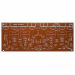
Hello to all members!im george from greece new member to the diyaudio... I want i little help with a pcb board from ebay... Lets start from the biginning...one friend has give me a gift a hand made greek amplifier from the late of 70s...
unfortunately from the inside of the amp missing the amplifier board all the other boards power supply preamplifier is in the box and is in excellent condition...now there is a huge problem this amplifier the power supply rail delivers + - 62 volts dc and the pcb from ebay the maximum input is + - 30 volts dc...
the first attempt was unseccesful i put all the parts in the pcb i plugged carefull in the amp turn on and then for 30 seconds i can listen from the speaker the music with the volume pot on the maximum the apear smoke and all the transistor was burn!!!!
3 questions can i modified the schematic to put self bias pot for adjust the bias? Can i modified the schematic on the mirror transistor for input signal sensitivity? Last question i want your opinions for any modification for work well with + - 62 volt dc power supply rail...
I will be grateful for any help you can provide
Attachments
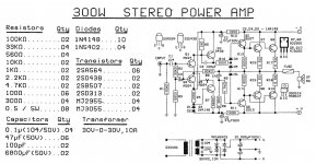
2n3055 and MJ2955 wont work with +/- 62 volts.
I don't know what the other transistors are so cant speak for those.
I don't know what the other transistors are so cant speak for those.
Thank you for the answer! The other transistors are the drivers 2sd 313 2sb 507 2sd 438 and 2sa 564 for mirrors... Sorry but i dont know how i upload the jpeg with the schematic if anyone knows the procedure of uploading a jpeg please tell me thank you
Oh this is from long ago, the seventies...
2N3055 is 60V max. The supply is +/- 62V, a total of 124V. As soon the output starts swinging (eg music), you fry the 2N3055/MJ2955. This power supply is NOT = NEVER suitable for this 3055/2955 circuit. Changing bias will not work either. Buy another power supply of +/- 30V instead.
The +/-62V unit needs another mainamplifier working on this supply. Guess why it was missing: blown up maybe?
How to attach images to your posts.
Very good indeed!
+/-62V, ie 124V rail-rail is only useful if it is also a 500Watt+ supply, ie suitable for a very large amp.
Also note that the ebay amp was rated +/-30V MAX, ie that would be pushing it. I would not run 2955/3055s higher than +/-20V, maybe +/-25V.
Also note that the ebay amp was rated +/-30V MAX, ie that would be pushing it. I would not run 2955/3055s higher than +/-20V, maybe +/-25V.
3281/1302 complementary transistors are 250V rated and good modern devices. Alas at +/-62V secondary breakdown limitations become important and this means needing several paralleled devices to be within the SOA limit, that board has 2 parallel, but 3 might be wiser.
A lateral MOSFET amp is more robust (no secondary breakdown), and needs extra volts overhead anyway, so that might be a possible approach.
A lateral MOSFET amp is more robust (no secondary breakdown), and needs extra volts overhead anyway, so that might be a possible approach.
I remember one of my early designs many moons ago. I didn't bother with decoupling the supplies near the amp. First glitch on the mains blew it up. You live and learn.
For 2n3055/mj2955 I wouldn't be going much above 45 volts. The old 1980's Maplin disco used those transistors and they were brave pushing it to about +/-55volts. It had good rail decoupling though. My disco amp was very loud and lasted for years until I sold it on.
I did a 100 watt update to the Maplin disco amp and used MJ15003/4 transistors.
I had a 2N3055/MJ2955 board that would blow transistors every few months with +/- 50V rails (35-0-35 transformer). Changed to +/- 40V and no more blew.
I would just drop the voltage. The 2SD313 isn’t a high voltage transistor either, and if the circuit wasn’t designed for higher voltage, you may have problems regardless of what transistors you put in there. Values may need to be adjusted. If you dont know how to analyze the circuit to do this properly, you’re just playing with fire. You may need more heat sink. Make that will need more heat sink. By the time you replace every transistor, change half the resistor values, put in higher voltage caps, add extra output pairs, buy a bigger heat sink, you may as well just start over with a bigger amplifier board made for it. Want to keep what you’ve got and get it working safely? Use a lower voltage supply. The most I would jazz this up would be with 2 pairs of TIP35C/36C per channel and +/- 40 volts. Beyond that I would doubt its safety.
Ok, they are ABSOLUTELY INCOMPATIBLE, period.now there is a huge problem this amplifier the power supply rail delivers + - 62 volts dc and the pcb from ebay the maximum input is + - 30 volts dc...
Which is the logic result.for 30 seconds i can listen from the speaker the music with the volume pot on the maximum the apear smoke and all the transistor was burn!!!!
What for? That PCB is absolutely incompatible with your supply.3 questions can i modified the schematic to put self bias pot for adjust the bias?
What for? That PCB is absolutely incompatible with your supply. [2]Can i modified the schematic on the mirror transistor for input signal sensitivity?
You can´t.Last question i want your opinions for any modification for work well with + - 62 volt dc power supply rail...
Which is: get a power amp which is happy with +/- 62V supply.I will be grateful for any help you can provide
That one is not.
I had a 2N3055/MJ2955 board that would blow transistors every few months with +/- 50V rails (35-0-35 transformer). Changed to +/- 40V and no more blew.
I remember reading that they used to test the Vce breakdown voltage on the old 2N3055 in house and select the ones with the higher breakdown voltages for use in higher rail amplifiers.
Woe be the technician that's not aware of this. I don't think it's a good idea to use a transistor beyond its rated breakdown voltage anyway, test or not.
Flea Bay has lots of amplifier boards that purportedly will work with these voltages. I certainly can't vouch for any of them (some are good I'm sure).
I bought some cheap "too good to be true" amplifier boards out of curiosity. They were made by Yuan Jing (I think that's how you spell it) and they worked better than I expected. Some of the parts were awfully cheap and I replaced them, which made a noticeable improvement. The chips (TDA something) were genuine; he must have bought a million of them to offer this price (less than $10 assembled). To his credit he used his own circuit which was arguably better (with fewer parts) than the datasheet circuit. But I could still build a way better circuit at home, for four times the price, with a TDA chip.
I bought some cheap "too good to be true" amplifier boards out of curiosity. They were made by Yuan Jing (I think that's how you spell it) and they worked better than I expected. Some of the parts were awfully cheap and I replaced them, which made a noticeable improvement. The chips (TDA something) were genuine; he must have bought a million of them to offer this price (less than $10 assembled). To his credit he used his own circuit which was arguably better (with fewer parts) than the datasheet circuit. But I could still build a way better circuit at home, for four times the price, with a TDA chip.
I recall a DIY power amplifier kit that was sold by a German vendor in the early 1970ies. This amp was advertised as 200 watts @ 4 ohms, featured two pairs of MJ2955's/3055's and rails of +/- 60 Vdc. The trick was they've put all power devices in series, same with the BD139/140 drivers.
The frontend was a more usual one, based on a Siemens application of 1971.
Best regards!
The frontend was a more usual one, based on a Siemens application of 1971.
Best regards!
Using selected 2n3055 goes from a bad idea to completely delusional. Even at the rated voltage (+/-30VDC), the SOA is very weak and will not survive being driven hard nor a reactive load. For reliable operation, these parts should not be used above +/-25VDC. Experienced techs know that "exact replacements" is often a bad idea. If it blew up once, it will happen again and this time it will be "your fault". To be successful at amp repair, you needed to be able to correct the foolishness of the original designer. 2n3773 was my choice to replace most any TO-3 failure, but just replacing parts is not enough. Often the amp was unstable etc, which required changes to prevent the failure mechanism. There were ~3 people in a town of 750K that professionals took their amps to for repair, because others just replaced parts, over and over until they scrapped the equipment or took it to one of us.
I expect that parts are better today, but it is still disturbing to read nonsense like using 2n3055 at or above 60V (+/-30V).
I expect that parts are better today, but it is still disturbing to read nonsense like using 2n3055 at or above 60V (+/-30V).
Using selected 2n3055 goes from a bad idea to completely delusional.
Agreed. I have an old Fisher amplifier on the shelf that uses 2N3055 output devices that runs on +/- 40VDC. It still works and hits hard too! I would never trust it in a system, but it provided 30 years of service. I got it when the guy died. I repaired it for him once a long time ago but I would never touch the output stage. It does have a truly enormous heat sink though.
Experienced techs know that "exact replacements" is often a bad idea. If it blew up once, it will happen again and this time it will be "your fault".
Absolutely.
Often the amp was unstable etc, which required changes to prevent the failure mechanism
I went through that replacing obsolete parts in a Nakamichi receiver. I did figure it out but in retrospect it was barely worth the sweat. For a cheaper unit it's not worth it at all in my opinion.
It's easier to design and build your own, instead of juggling poles and tweaking bias currents in an obsolete, inferior design. The rabbit hole can be deep and DIY is more straightforward, in my opinion. And make no mistake, some "consumer grade" equipment is quite inferior.
Fame goes that RCA's 40636's were 2N3055's that were selected for to cope with higher Uce. Does this hold true?
Best regards!
Best regards!
Yeah, look at the schematic of the Armstrong 621. That was single rail 75 v. I saw the RCA 40636 datasheet once, but it was in the boss's databook and mine is 1975 after they quit selling those. Dynakit ST120 used 40636 too @ 70 v. They used to run the rail so high because the gain was so bad in 1966, they needed it to get to 60 W/ch out.
Nowadays an MJ15015/16 is the same price twice the Vceo (120) and has an actual soa chart, so buy the real deal. (may not be available except fakes in Eurasia). Downside, they are way fast, 4 mhz, so you need to install 5-10 ohm wirewound base resistors in old designs that might oscillate.
Nowadays an MJ15015/16 is the same price twice the Vceo (120) and has an actual soa chart, so buy the real deal. (may not be available except fakes in Eurasia). Downside, they are way fast, 4 mhz, so you need to install 5-10 ohm wirewound base resistors in old designs that might oscillate.
Last edited:
now there is a huge problem this amplifier the power supply rail delivers + - 62 volts dc and the pcb from ebay the maximum input is + - 30 volts dc...
the first attempt was unseccesful i put all the parts in the pcb i plugged carefull in the amp turn on and then for 30 seconds i can listen from the speaker the music with the volume pot on the maximum the apear smoke and all the transistor was burn!!!!
Maybe I am missing something, but what were you thinking to hook up a 30V amp to a 62V supply??
I normally try to avoid addressing personally but this is soooo stupid!
Jan
Maybe I am missing something, but what were you thinking to hook up a 30V amp to a 62V supply??
I normally try to avoid addressing personally but this is soooo stupid!
Jan
But he did turn it on carefully !
- Status
- Not open for further replies.
- Home
- Amplifiers
- Solid State
- Transistor amplifier pcb mj2955 2n3055