Early 70's I'd say. I was young in those days, unaware of quantummechanics and relativity on universal scale. Cute upsidedown drawing, from the beginning of transistorcircuit publications. Nothing wrong actually, solid topology save the discussed powerrail specs.
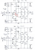
Curious connection of node with R2-R3-C2, not often used anymore. And that D3... something is missing there! How's Q5 biased actually???
Curious connection of node with R2-R3-C2, not often used anymore. And that D3... something is missing there! How's Q5 biased actually???
Schematic error - looks like the 100 ohm resistor is supposed to connect to the node at D3 and Q5 it’s the only way it could work. R2-R3-C2 looks like a bootstrap to raise input impedance, to prevent Zin from being dominated by the bias resistor. It does look ok for +/- 30 volts. But the schematic shows 30-0-30 AC, which is +/-42 - a bit high for TIP/MJE3055 which are the actual plastic part #’s, not the 2N which is the TO-3. With +/-42vokts, TIP35C/36C should be used. They are just as cheap and readily available. This would result in a good reliable amp, provided you never shorted the speaker wires.
You’re no fun - I wanted to see how far it would embed itself in the ceiling.
Reminds me of my days as a student electronics engineer.
In the mornings we did theory and in the afternoons built up circuits associated with that theory.
We all had to build a small single stage amplifier.
As the afternoon went on there was bang after bang as people had put in electrolytics the wrong way around.
Maybe I am missing something, but what were you thinking to hook up a 30V amp to a 62V supply?
With a transformer spec of 30-0-30 Vac, one might have assumed 60V in total somewhere, so 60-0-60 vdc will suffice anyhow. Just be carefull to ignite the gunpowder!
In the distant past, there were many designs for complementary 2N3055/MJ2955 or quasi complementary 2N3055/2N3055 power transistors because the parts were cheap, available everywhere and locally at least, a standard E-I laminated transformer of 120VA with 56VCT VAC secondary winding was commonly available and resulted in nominal 40VDC rails. This was reliably safe with 2N3055 transistors in a stereo build because the transformers would allow the rails to sag sufficiently under load to protect them. It was the basic formula for many magazine designs over the 1970-1990s period and found its way into professional audio industry products for many years too, so there's no question about the safety of the 2N3055 power transistors, even from several sources, when using the appropriate type of power supply.
Unfortunately, this doesn't apply to many modern style power supplies where we use large toroidal transformers, massive smoothing caps, fake semis and the general overkill that DIYs typically apply. Almost certainly, there will be problems if you assume the schematic is all you need to build the amp. or that a 30+30VAC toroidal transformer is OK. They aren't 🙁
Unfortunately, this doesn't apply to many modern style power supplies where we use large toroidal transformers, massive smoothing caps, fake semis and the general overkill that DIYs typically apply. Almost certainly, there will be problems if you assume the schematic is all you need to build the amp. or that a 30+30VAC toroidal transformer is OK. They aren't 🙁

the transformers would allow the rails to sag sufficiently under load to protect them.
They sure did. Cheap equipment with inflated wattage claims were built like that until around 10 years ago or so.
I reverse engineered some "hi-fi" "50 + 50 Watt" cheap stereos. All of them worked like this. They all had a TDA chips with shockingly small heat sinks and they all had wimpy transformers and capacitors. They would produce 50 watts for a every short transient (milliseconds) and when the going got rough they only produced around 12 watts a channel.
Unfortunately, this doesn't apply to many modern style power supplies where we use large toroidal transformers, massive smoothing caps, fake semis and the general overkill that DIYs typically apply. Almost certainly, there will be problems if you assume the schematic is all you need to build the amp. or that a 30+30VAC toroidal transformer is OK.
Yes we do.
I built a simple, conventional amplifier ("blameless") that runs off +/- 35 volts DC. The power supply is quite stiff. It's fan cooled. For only around 40 watts/channel into 8 ohms it hits real hard. Super clear and no problem driving 8 ohm speakers loud. Hasn't blown up yet. Sure sound a lot louder than "50 + 50 watts" Magnavox crap.
300 watts of output power from just two pairs of those devices, working at rails of +/- 42 Vdc maximum? That's PMPO, I'd say - Purely Mythical Output Power 😀.
Best regards!
Best regards!
150 watts, per channel, into 2 ohms. There is an old rule of thumb that works pretty well for concentrically-wound EI core transformers. With 20,000 uF of capacitance, when the total amplifier output power equals the volt ampere rating of the trafo, the DC output voltage falls to the unloaded AC RMS voltage. Thus, with 300 watts output will make a 300 VA, 30-0-30 trafo put out +/-30 volts DC. Unloaded it will be +/-42, and to produce 150x2 Into 2 ohms, +/- 24 V peak is required from the amplifier. I have no doubt that it will produce this. This is what Ian was referring to, and exactly what the designer intended. With a toroid, you may get this at 4 ohms, but chances are it will come up a bit short unless you oversize ir (small toroids drop just as much under load as EI, but big ones do better for a given VA size). Then you will be blowing output transistors unless you upgrade to the next size up (TIP35C).
On Sundays, I drink some tea to start with, and a fine muscat later on.
The rest of the day I spend doing useless things like drawing circuits and analyzing them.
I'd rather frame it as a 90/8 amp, for parties and fun only.
Yep. I wonder if these are mistakes or a deliberate error to sabotage copy-cats. Or maybe a schematic generated by tracing someone else's board with mistakes, ie the vendor has little of no tech staff? I have seen lots of deliberate errors in IC equivalent circuits, in chip pdf data files.
Years ago I used to draw schematics on paper . Spice is more fun and productive cause you discover lots of issues and hopefully how to fix them without loosing any magic smoke.
Now Georgealfaromeo (first post) can check if the traces are ok on his board:
"300W STEREO POWER AMPLFIRE".
"300W STEREO POWER AMPLFIRE".
If I interpret his interpretation correctly, it was playing music for 30 seconds then poof. If the cap were backwards it would have exploded and sent the can into the ceiling immediately - possibly continuing to play music. The diode connection error would have prevented the PNP half of the output stage from working at all, producing at least 50% distortion. My guess is these were actually correct on the PCB. The schematic was drawn by some idiot who didn’t even know what a diff pair is. Threw me for a loop at first glance, thinking it was some sort of vbe compensated Singleton input stage. Those do exist and sound pretty nice.
Still, a proper schematic is probably a good idea to have in the thread somewhere. It’s not really a bad circuit for 30 or 40 volt rails with the right parts.
On +/- 62 volts I’m surprised it lasted as long as it did. But most 3055 type transistors DO handle over 120 volts in the OFF state. They dont guarantee any current capability above 60. And from the fake C3282’s I’ve seen with 3055 dies inside they usually don’t. I guess those particular units could handle *some*.
The amp, the amp, the amp is on fire!
We don’t need no water let the M***** burn!
Well, the amp is supposed to be used for parties and fun isn’t it?
OTOH, 90 watts isn’t exactly enough to set the roof on fire. Add a couple of zeros.
We don’t need no water let the M***** burn!
Well, the amp is supposed to be used for parties and fun isn’t it?
OTOH, 90 watts isn’t exactly enough to set the roof on fire. Add a couple of zeros.
Now that is curious coincidence while doing some research about a Luxman R1030 receiver: I found this circuit serving as a main stage in the serviceman.
Rails on +/- 30.7V
One can conclude that the circuit design is ok, but carefull choise of components is important too.
Rails on +/- 30.7V
One can conclude that the circuit design is ok, but carefull choise of components is important too.
Attachments

- Status
- Not open for further replies.
- Home
- Amplifiers
- Solid State
- Transistor amplifier pcb mj2955 2n3055