People who don't understand electronics might not realise that this is pure bunkum.Max Headroom said:The drivers do return the voice coil magnetically stored energy but this is passively 'caught' in the RC networks and prevented from traveling up the speaker line and being 'synthetically' caught in the amplifier output stage.
So if the voice coil inductively stored energy does not transfer to the amplifier, where the hell does it go Einstein ?.People who don't understand electronics might not realise that this is pure bunkum.
Dan, has Joe really only been talking about Zobel network/Boucherot cell, because that's what you are describing?
Ok......first impressions of the 6r/0.47 zobel are sharper focus and a tighter sound but might be a little soft on top, would less R help that?
Gonna have to play with this one.....it definately helps the ‘stage’ which might be from the phase leveling aspects?
Gonna have to play with this one.....it definately helps the ‘stage’ which might be from the phase leveling aspects?
Why do you think that it "does not transfer to the amplifier"? The output impedance of the amplifier is a lot lower than 6 Ohms, why would currents take a much higher impedance path? Have you also introduced a series element?So if the voice coil inductively stored energy does not transfer to the amplifier, where the hell does it go Einstein ?.
An ohmic material is one for which Ohm's law is true, to a considerable extent i.e. voltage and current are approximately proportional.
"Approximately" is open to interpretation. Under normal listening conditions a speaker motor could possibly be considered weakly non-linear and fit the description.
In the example of metals, pure metals have a conductivity almost proportional to absolute temperature (in many/most) cases. So even in some thing as mundane as home wiring the heating effect can't be ignored.
I think if you go back far enough you will find Ed considering even relatively good film resistors with -100dB third harmonic distortion as not ohmic.
Last edited:
You can try juggling both values R up, C down but yes less harsh tops and clearer depth info is the result IME.
Of course it is "a little soft on top" you have added a low-pass filter.Ok......first impressions of the 6r/0.47 zobel are sharper focus and a tighter sound but might be a little soft on top, would less R help that?
Gonna have to play with this one.....it definately helps the ‘stage’ which might be from the phase leveling aspects?
So if it’s old hat, has anyone implemented it commercially before? Examples?
Lets talk about impedance flattening. If you look at common speaker crossover or its impedance, you will see that there are impedance increase towards HF due to tweeter voice coil, and there are bumps at LF due to woofer resonance and port resonance.
To solve the impedance issue at HF, a zobel/boucherot is used. This is cheap as you need only RC with small C. This is more common than not, but I always prefer to avoid it unless the amp is not fully stable without it. My standard R value is 12 Ohm instead of the more common 10 Ohm.
To solve the impedance issue at LF, and RLC is used and you need big L which is expensive. The cost is probably the reason why it is not common commercially or even DIY. Quite a cost increase with 'improvement' that in many situations can only be heard by the golden ears like you.
Now, would you prefer to use any impedance flattening method at LF? It depends on for example your design skill, how you can get a good sound at a given cost regardless of technology or trick that you are free to use. Because impedance flattening cct will lower load impedance it can be a good idea to avoid the effect by using woofers in series. While distortion is also lower (due to lower cone displacement) the cost is increased.
I think people rarely know that inaccurate amps can subjectively outperform accurate amps at HF (and mids and midbass). But if your speaker should deliver bass extension not found in two-way designs, accurate amps ime will outperform inaccurate amps convincingly. If you had to use a single amplifier to cover this low bass, and you really want to use flea/tube amp, this impedance flattening approach does probably make sense. But my preferred solution is to design a better amp and/or use multi amping.
"
I think if you go back far enough you will find Ed considering even relatively good film resistors with -100dB third harmonic distortion as not ohmic.
Depends on the test conditions. Higher power and lower frequency usually increase distortion. But practically I would expect a resistor that stayed in tolerance to be ohmic. IE a 1% resistor would need to stay better than -40 dB at 20 hertz and full rated power.
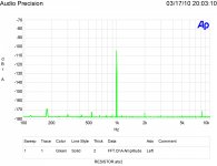
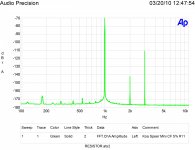
As promised some more data.
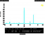
First is a Dale RN65C1001FB14, Second is an Audiophile tantalum type, Third is a naked bulk metal Vishay and the last is a cheap Xicon 1/4w 1K metal film.
Points of interest are the Dale is the best, the bulk metal unit is not as good and the really cheap Xicon is better than almost all the rest tested.
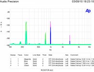
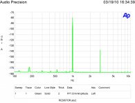
Frequency and level effects are show with the naked bulk metal film Vishay. Note that thermal distortion increases as frequency decreases for third harmonic distortion.
Or price isn't a good guide!
Attachments
Last edited:
As promised some more data.
Set aside it is unclear what these charts are showing, I don't trust a iota your measurements. You need to come up with more, as far as I can tell you used an AP equipment, that's it. Or very possible misused.
And please don't point to your "publishings" they are not worth the paper they are printed on.
So if the voice coil inductively stored energy does not transfer to the amplifier, where the hell does it go Einstein ?.
It fights the current the amp want to put through the voice coil so the amp has less work to do, not more.
This is an interesting carbon film resistor. Note the base spreading at the fundamental. That is a sign of 1/F noise.
That would excess noise modulating the fundamental, with some old tube amps and really bad carbon comp resistors they say it is audible.
Resistors are made out of real materials and with real processes, they have potential non-idealities at some scale. It really has nothing to do with Ohm's law, no need to even bring it up. Module designers discovered decades ago that mounting resistors vertically to save space was a bad idea because you unbalance the thermocouples at the termination and we put it in an app note. We didn't preface it with "Ohm's law isn't".
Last edited:
As to impedance compensation for individual drivers, this may be useful in order to make a passive xover work properly. For example, the rising impedance of a woofer renders the coil in the xover less effective and makes it impossible to get the desired filter slope. A zobel is your answer. Another situation would be a tweeter. When filtered relatively close to the resonance frequency, an lcr in parallel may be required to present the correct impedance to the xover. In these situations, impedance compensation may be a useful tool, but only at the individual driver level.
Impedance compensation before the xover is putting the horse behind the carriage.
Impedance compensation before the xover is putting the horse behind the carriage.
- Status
- Not open for further replies.
- Home
- Member Areas
- The Lounge
- John Curl's Blowtorch preamplifier part III