The question still remains that paralleling at the speaker with a R (50-75 Ohms) makes an audible difference compared to no added R.
Why?
THx-RNMarsh
This does not make any sense at all, just on the basis of some anecdotal information, except perhaps in the case of a pathological amplifier.
It is easy to measure distortion produced by a loudspeaker. That would be the first measurement I suggest. There cannot be a difference, only if the amp can't cope with the lowered impedance. The second would be the FR. The worse the amplifier, the lower the SPL, and the bigger the bumps around resonances, would be my prediction. If you take an amp with a sufficiently large damping factor, the two FR responses will be identical.
If you think these measurements will not reveal anything, than at least a controlled listening test should be conducted.
Originally Posted by RNMarshThe question still remains that paralleling at the speaker with a R (50-75 Ohms) makes an audible difference compared to no added R. Why?
I am running RG-59 75R coax cable (all copper no platings) as speaker cables with 75R at each end. I found the coax to be nice improvement compared to fig8 lamp cord terms of clarity and detail and 'ease' and realism in in the sound. Addition of the 75R resistors to terminate the coax resulted in removal of a very low level 'hash' revealing even more detail and allowing distinctly better focus, positioning and depth rendering.This does not make any sense at all, just on the basis of some anecdotal information, except perhaps in the case of a pathological amplifier. If you think these measurements will not reveal anything, than at least a controlled listening test should be conducted.
I compared two resistor types ie 1W carbon film and 0.6W MF and the difference is audible with MF sounding 'clean' and the CF sounding warm but coloured. I don't know if the differences are due to chemistry or parasitic inductance or tempco or what and I know this observation seems odd according to theory but one proof is that when I over drove the system and killed one resistor the shift in balance/imaging and change in 'tone' was distinctly audible and this caused me to investigate and find the dead resistor. The amplifier is a high quality Denon receiver and representative of decent home AV systems so of course is not SOTA but it is indicative of load dependence in such typical systems or is it RF susceptability ?. Before the usual objections this is a dirt cheap 50cent quick no brainer experiment and I recommend that you guys try it just to satisfy curiosity if nothing else and if anybody finds it to be beneficial as I have that would be interesting.
I won't follow every nit-pick and criticism printed here, because most are trivial and virtually meaningless. However, whether Joe has done something useful, or not, is not for me to determine, nor any of the rest of you, without seriously trying it first.
 Dan.
Dan.
Last edited:
Sorry, both of you are wrong.
Sorry, usually at least one of me is right.
Back-EM-"Force" is IMO a dangerous term as it denotes a voltage(!) and not a mechanical force, therefore it often get's mixed up with the mechnical force which is created when this Microphonic Voltage (preferred term) has some resistance (driver's Re + any external source resistance) to work upon, which converts it into a current which in turn creates a mechanical force on the cone (which happens to be in opposite direction than the force applied via some current to get the cone moving in the first place).
Summed up: Back-EMF is an exact measure of the velocity of the cone. With the SPL (==acceleration) being a 2nd order highpass, velocity then is a 2nd order bandpass function (one integration). Which means it is highest at the corner frequency, no matter how that corner is established.
You seem confused. Words are not dangerous, their misunderstanding is (or the concepts they stand for). Everybody who wants to put the effort into it can know its proper meaning Electromotive force - Wikipedia. The word ' force' may be misleading to some, but this Wiki explains it well. It would perhaps be clearer if it were replaced by 'induction', but EMF is the agreed word for the phenomenon.
In the case of a bass reflex enclosure, EMF is lowest at the corner frequency of the enclosure. And it is highest at the points where the speaker is in resonance (one the closed enclosure resonance point, the other where pipe and speaker resonance mutually reinforce). None of them are even near the corner frequency.
I don't get a handle on what you mean with your 'Microphonic voltage' etc. Since this is not an existing term, you may wish to define it first, including in what sense it differs from 'EMF'.
Mechanical Resonance has nothing to do with it. Resonance has effect on the current needed to sustain motion at that frequency. At resonance, current is lowest because the cone is already quite moving like we want it to move with little current "refill" needed to keep it moving. OTOH, when swapping the phase of an exitation at resonance suddenly, a large current is needed to stop the sympathetic movement of the cone and revert it properly if we want the cone movement to follow the exitation voltage signal.
This seems to be an interesting case of anthropomorphisme. How does this current know how much it has to 'refill'.
Of course, when you reverse the phase of exitation at resonance, EMF will detract from the impedance and a large current will flow for a brief period of time.
It's all in the following most basic equation:
At any point in time
e(t) = k*v(t) + Ze*i(t),
e(t) is the terminal voltage, v(t) is the cone velocity, k is some constant, i(t) is voice coil current, Ze is the static VC impedance (== Re at low freq).
What it means is this: To induce any change in motion the amp must always apply a voltage corresponding to the microphonic voltage *plus* the voltage required to produce the needed current through Ze. Around resonance, this required current is smaller than at other points which yields a higher terminal impedance e(t)/i(t) (now being sinusodial functions).
It also shows that the driver has more intrinsic local feedback (velocity self-control) when Ze is getting lower and/or microphonic voltage is getting higher (actually, it's not Ze but rather Ze/(BL)² which determines both the effectiveness of the motor force and the microphonic voltage). A small difference between applied voltage and self-measured velocity is going to produce a large correction current until the microphonic voltage (velocity) matches the input signal.
I am not going to figure out what you are trying to say, and not because I don't want to. One thing for sure is that you at least need complex algebra because cone velocity, voltages and currents are all out of phase with each other.
Last edited:
<snip>
I really don't care to get into one of your usual arguments over semantics. You're reading into things I did not say regarding the JTAG port. There also appears to be nothing under the coating, I don't know what you are talking about with that comment.
You responded to a post by syn08 where he complained about the (obviously he meant silly) approach to EMC by the 'conformal' coating and shielding of ICs, for a pcb "otherwise perfectly good engineered" with:
"Conformal coating, tin foil. Of course, all the jumpers are still untouched and so is the 20 pin JTAG connector among the others that have been pointed out. What a joke."
Therefore my question as it seems to be an inherent contradiction.
You might call it "semantics", but isn't it in reality not just asking for evidence for some quite brisk statements?
If it were just comments about "it appears to be ....." it would have been nice to include an indication for it.
thought my opinion on this was clear. I'll reiterate it for you if not:<snip>
Nothing wrong with opinions ..... 😉
Last edited:
No. The reference point is current drive i.e. no electrical damping, just the speaker's own mechanical damping. This is DF=0. Then higher DF (lower amp output impedance) means more electrical damping.Joe Rasmussen said:Let's face it, DF is the idea that the amplifier can add damping. Since the reference point is zero Ohm and if the amplifier's impedance it is a positive number, then the amplifier can only worsen damping.
Maybe you have changed an RF resonance? Such an RF resonance should not be there, of course, but amps are not always perfect in this way because too few audio designers know anything about RF. Maybe the sound only 'changed' because you knew the resistor was present?Max Headroom said:So you put a say 20R resistor across the loudspeaker terminals and despite the amplifier having decent damping/output impedance and no current limiting operation the sound changes......why ?.
Sigh. OK, it seems we have to teach a world-class audio designer one of the basics. For DF to be useful it has to be at a low frequency, say 100Hz. It has to be scaled by the nominal speaker impedance, not necessarily 8 ohms.john curl said:Now, what is damping factor? It is simply the effective output impedance of the amplifier at some nominal frequency, let's say 1KHz, divided into 8ohms. That is it, so far as I know.
Who cares about HF damping factor? At those frequencies there is quite weak coupling between electrical and mechanical domains in the speaker, so no use for and no need for electrical damping.the effective damping factor at 10KHz or above was not very low.
Most people reckon that DF of 20 is enough, beyond that you get diminishing returns.But is a DF of 100, better than a DF of 10? Maybe.
Of course. A speaker design which has sufficient mechanical damping needs little or no electrical damping. However, most speakers are designed for voltage drive so need high DF (i.e. greater than 20).Now is a modestly high DF always the best? No. I have experimented with a DF of 1, on a particular direct radiator acoustic suspension speaker and found it sounded best. It was unfortunate, because the added series resistor, about 3.3 ohms threw away significant power, but when 2 or more of us heard it, it was obvious that the series resistor should remain.
and completely unnecessary.Now, maintaining a good damping factor over the entire audio frequency range is actually fairly difficult
The question still remains that paralleling at the speaker with a R (50-75 Ohms) makes an audible difference compared to no added R.
Why?
THx-RNMarsh
Flattens the current phase angle.
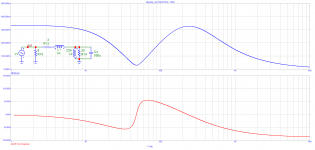
See below, while this is a single driver (Red), you can see what happens when you add a significant parallel resistance (Blue), 8 Ohm driver and 8R parallel resistance, so it becomes a nominally 4 Ohm load. Fine for most amplifiers.

This works even better than adding series resistance, but is also more wasteful than using series impedance.

This time series 18R added, but compare with the above and parallel is the better result. Also, voltage swing is severely curtailed with large series resistance.
I know this is going to cause flak, but this is about the amplifier 'reacting' to the speaker's load. The Re (DCR) of the speaker will be about 5-6R and anything above that in the impedance measurement is caused by back-EMF, basically a voltage source.
If you can whistle into the speaker a tone that matches that from the amplifier while measuring the current, and as you increase whistling (this is of course a thought experiment), then you will see a reduction in current from the amplifier.
That back-EMF is also what causes the current phase angle, since the Re part of the impedance cannot. The Re is only resistance and is not reactive, indeed the Re value limits the effect of back-EMF on the amplifier.
This may be difficult for some to grasp, but it sure is not rocket science.
Flattens the current phase angle.
Repetitive nonsense. If you add a parallel resistor to a voltage output, speaker current does not change at all. See R15 stepped from 8ohm to 1008ohm. You are trying to manipulate reality and people. Speaker current goes through R13. Only i(R13) + i(R15) is changed, which is unimportant IF you have an amplifier with high DF and output current.
Attachments
There seems to be too much snake-oil selling going on at the moment from the usual suspects, a little bit is amusing but they've taken over and others are largely quiet, due to boredom probably. Still, hat's off to those who refute it, it's a shame it's necessary.
The other day, when you were talking about 'circulating' currents, was that also about the amp?but this is about the amplifier 'reacting' to the speaker's load.
There seems to be too much snake-oil selling going on at the moment from the usual suspects, a little bit is amusing but they've taken over and others are largely quiet, due to boredom probably. Still, hat's off to those who refute it, it's a shame it's necessary.
Ideally, everybody else should temporary leave and let them sell the snake oil to each other. And FUD each other.
That would be quite a show to watch.
No. The reference point is current drive i.e. no electrical damping, just the speaker's own mechanical damping. This is DF=0. Then higher DF (lower amp output impedance) means more electrical damping.
Show me where it says that. Asking nicely.
At European Triode Festival 2017, Menno vander Veen brought a modified Putzey Class D amplifier (I think it was the NC generation) and it had multiple output impedances, zero, I think 6 Ohm and I definitely remember the highest was 18 Ohm. A bunch of people in the room, they all preferred when the amplifier was not a voltage source. Menno preferred 18 Ohm himself.
If these tests were not level matched and individually equalized to the same frequency response this is no more than a "fun" exercise no better than the highly criticized "forum ABX". See for instance the Carver challenge.
Yes, 6 ohm and 18 ohm output impedance will have a nice bass-boom boost. Some may prefer it 😀. No dry or sterile sound, then 😀 😀
Repetitive nonsense. If you add a parallel resistor to a voltage output, speaker current does not change at all.
We were here exactly a year ago, it's time again for the amplifier does not see "the reactive impedance current".
Oh yeah, and amplifier output current phase is flattened. Why not to use a 1 ohm parallel resistor? Even more flat amplifier output current!!! 😀😀
If I were Joe, I would go for it. Or let's use a 1 milliohm shunt.
If I were Joe, I would go for it. Or let's use a 1 milliohm shunt.
No, back EMF is maximum at resonance peaks. It is just that there is no phase angle at that particular point. Left and right of the resonance peak there are. EMF is just the voltage produced by the voice coil moving through the magnetic field. There is always EMF generated when a speaker produces sound, not just at resonance. It is quite easy to calculate how much Voltage Generated in a Moving Wire
Agreed. Motional back-EMF, mainly at LF. Inductive back-EMF a la Faraday causing that typical rising impedance. And then microphonic back-EMF which can also be caused by resonances etc. A badly designed speaker with high distortion will cause damaging back-EMF that has to be dealt by the amplifier.
Never seen an amplifier that could not cope with speaker current around resonance being out of phase with voltage. Don't forget that around resonance, impedance is highest because of the generated EMF and so the load becomes easier on the amp, not more difficult. Watt for Watt, you can produce the most acoustic power out of a loudspeaker at resonance. Thanks to back EMF, loudspeakers are linear above resonance under voltage drive.
If you look at the amplifier requirements as simply a logistics exercise, then you are correct. Absolutely. So on that topic, we are in agreement.
But there is another mechanism at play here. There is something happening and there seems to be a reluctance to consider it.
What that mechanism is, is not related to the capacity of the amplifier to behave in a linear way on the voltage side. On that side of things, if the logistics are in place, beefy output stage and power supplies, there indeed is not a problem.
This [other] mechanism is related to the simple fact that the force is actually the current and not the voltage. The driver is a current device. So yes, you are right that there are frequencies where the load is entirely resistive and you were right to correct him. But we need a more complete picture of how the amplifier reacts to the speaker, the speaker distorts the current of the amplifier and then that altered current affects the speaker. Speaking pictorially, a messy situation.
Mind you, add to the Re of the speaker, you will reduce that, and if the amplifier is held at zero degrees current phase angle, that would be a real improvement. The speaker will still distort, but it will have difficulty is distorting the current of the amplifier.
Parallel resistance is arguably better than series.
Last edited:
That appears to be your definition of back EMF, so it is a tautology.Joe Rasmussen said:The Re (DCR) of the speaker will be about 5-6R and anything above that in the impedance measurement is caused by back-EMF, basically a voltage source.
Putting an 8 ohm resistor in parallel with a nominal 8 ohm speaker may reduce any impedance peaks, but it also deepens any impedance troughs. Whether this makes the load easier or harder to drive depends on the details of the amp, but in many cases it will be backwards step. Nothing of any consequence here.
EEs call this 'amplifier output impedance'.I know this is going to cause flak, but this is about the amplifier 'reacting' to the speaker's load.
Nice to be patronised by someone who thus far has given us no evidence that he understands complex numbers and hence is capable of understanding impedance.This may be difficult for some to grasp
You show me where you got your opposite claim. Mine came straight from 'first principles' thinking, which I guess is what you claim to be doing except you keep getting the basics wrong.Joe Rasmussen said:Show me where it says that. Asking nicely.
Merely repeating confused thinking over and over again does not make it more likely to be true, but it may pick up a few naive fans. Good for marketing; bad for science.This [other] mechanism is related to the simple fact that the force is actually the current and not the voltage. The driver is a current device. So yes, you are right that there are frequencies where the load is entirely resistive and you were right to correct him. But we need a more complete picture of how the amplifier reacts to the speaker, the speaker distorts the current of the amplifier and then that altered current affects the speaker. Speaking pictorially, a messy situation.
Mind you, add to the Re of the speaker, you will reduce that, and if the amplifier is held at zero degrees current phase angle, that would be a real improvement. The speaker will still distort, but it will have difficulty is distorting the current of the amplifier.
Parallel resistance is arguably better than series.
Nice to be patronised by someone who thus far has given us no evidence that he understands complex numbers and hence is capable of understanding impedance.
Well we call it "real" and "imaginary" part, he is just holding us to the strict use of imaginary. 😀
the speaker distorts the current of the amplifier and then that altered current affects the speaker
This is wrong, where are you getting it from or are you just making it up?
There seems to be too much snake-oil selling going on at the moment from the usual suspects, a little bit is amusing but they've taken over and others are largely quiet, due to boredom probably. Still, hat's off to those who refute it, it's a shame it's necessary.
Matt, you can bring a horse to water, but you can't make it think.
- Status
- Not open for further replies.
- Home
- Member Areas
- The Lounge
- John Curl's Blowtorch preamplifier part III