Hi Glenn,
Have you checked the two capacitors that block DC on the inputs of the LM7000 yet? A leaky capacitor will upset DC conditions and kill that LO input. Something I have seen before.
If the LM7000 (or any similar chip) does not receive the LO input, it opens the "feedback loop" and it doesn't know where it is. Most commonly locking the Vt line up high. It is possible to have multiple faults and it wouldn't surprise me to see defective coupling capacitors. Those ceramic caps in your tuner are probably really cheap ones rated for 25 V. Their failure rate is a lot higher than the normal ceramic capacitors we run into rated for 100 V or higher. I'm even suspicious of the parts rated for 100 V.
As for the tuner pack, the failed transistor will be obviously dead when checked with the diode check feature in your meter. Remember that you have to pull them to test them.
-Chris
He pulled the FM pack so no more LM7000 loading anymore. C13 is your o/p to the LM7000.
It is pretty easy to test Tr4 for bias while powered up. Not to say even if properly biased it has sufficient gain to sustain oscillations or is loaded down too much by the mixer or the buffer which cap coupled too. Everything is suspect.
methods of elimination &/or substitution.
It is pretty easy to test Tr4 for bias while powered up. Not to say even if properly biased it has sufficient gain to sustain oscillations or is loaded down too much by the mixer or the buffer which cap coupled too. Everything is suspect.
methods of elimination &/or substitution.
The Sanyo LM7000 spec says that, if I look, 0.1 to 1.5V rms for both Am & Fm inputs.
Looking at the parts spec tells you in some cases more than the service manual does or in better terms............
Thanks Rick, so it really does look like the local isn't running. That seems a definite 'fault number #1' then.
Scope shot was here but this was just stray pickup:
Yamaha TX540 tuner not tuning
I'm still a bit suspicious now though of why AM doesn't work normally when under the tuners control. What is stopping it? I suppose ultimately there is lots of hidden internal inter-dependency between chips such as the LM7000 and the uP and the I²C or similar data bus.
Little compressed disc ceramics can give certainly you the run around when they go leaky.
Hi Rick,
I figured he could test those parts while the tuner pack was out. A leaky one would bias the input for the oscillator into cutoff. I can't remember if that would load down the oscillator output. Probably not.
-Chris
I figured he could test those parts while the tuner pack was out. A leaky one would bias the input for the oscillator into cutoff. I can't remember if that would load down the oscillator output. Probably not.
-Chris
Mooly, in regards to your question:
When you tuned the pot manually and if you had AM selected on the tuner, did the tuner frequency display change as you altered the pot?
Answer is no. Have not figured out how to use the quote function at this point! Glenn
When you tuned the pot manually and if you had AM selected on the tuner, did the tuner frequency display change as you altered the pot?
Answer is no. Have not figured out how to use the quote function at this point! Glenn
Hi Glenn,
You can do this manually by typing [.quote] at the beginning and [/.quote] at the end, the "quote" would be in caps and without the periods.
-Chris
Just copy and paste the passage you want to quote. Then, highlight it and then click on the top right symbol that looks like a text balloon you used to see in comics.Have not figured out how to use the quote function at this point!
You can do this manually by typing [.quote] at the beginning and [/.quote] at the end, the "quote" would be in caps and without the periods.
-Chris
Hi Chris,
Not sure which caps are the coupling caps. Glenn
Please check or just replace those coupling capacitors to the LM7000.
Not sure which caps are the coupling caps. Glenn
Hi Glenn,
The capacitors that connect to pins 13 and 14. AMin and FMin. I'm not looking at a schematic at the moment, but that information should send you in the right direction.
-Chris
The capacitors that connect to pins 13 and 14. AMin and FMin. I'm not looking at a schematic at the moment, but that information should send you in the right direction.
-Chris
OK. That's C8 and C104 connecting to pin 13. C8 is in series while C104 goes to earth so assume coupling cap is C8. Not seeing any caps connecting to pin 14 (Fmin)- goes straight to Osc pin on front end. Glenn
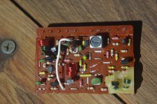
Have attached image of tuner board. The OSC pin is top right and Vt is four along from that. All other pins went to earth as far as I can recall. Does that make sense given that FB and IF must connect to two of these pins according to schematic? I am not seeing any obvious cracked solder joints on the underside. Glenn
Attachments
Hi Glenn,
The oscillator transistor is the one buried in wax. Take care pulling it so you remember which way it goes in. Test it, then test the other two transistors, one at a time.
-Chris
The oscillator transistor is the one buried in wax. Take care pulling it so you remember which way it goes in. Test it, then test the other two transistors, one at a time.
-Chris
Mooly, in regards to your question:
When you tuned the pot manually and if you had AM selected on the tuner, did the tuner frequency display change as you altered the pot?
Answer is no. Have not figured out how to use the quote function at this point! Glenn

And it opens to this 🙂

Hi all, have removed the oscillator transistor. Part number is I211 with maybe a 26 under that or 2K- hard to read. I think it tests OK with diode tester. Taking centre pin as base (negative), am getting readings on both the other pins (emitter and collector- positive lead). So this is a PNP? Getting OL when reverse the leads. Getting OL with leads on emitter and collector (outer pins) whichever way they are connected. Glenn
Mooly, in regards to your question:
When you tuned the pot manually and if you had AM selected on the tuner, did the tuner frequency display change as you altered the pot?
Answer is no.
I'm still reading it all and trying to piece it together. That could actually be a valid result. The uP (microprocessor) doesn't tune by altering the varicap tuning voltage Vt directly, it will work by selecting a known (whatever you tune to) frequency and comparing the local osc signal to that known frequency within the uP. When the two match (although there may be a lot of frequency division within the chips) it 'knows' you are tuned correctly. The Vt line is at whatever voltage is needed to bring that state about.
Anyhoo... this is getting heavy from a diy perspective and I'm still not happy that AM doesn't work in its own right seeing as the tuner operated OK with a manual tuning voltage.
Did you try looking at the local oscillator output from the tuner with the LM7000 input pin disconnected? This is similar to looking for a leaky coupling cap but I'm also wondering if there is an internal issue within the LM7000 that is pulling it down.
Hi Mooly,
No, did not do that. Glenn
Did you try looking at the local oscillator output from the tuner with the LM7000 input pin disconnected? This is similar to looking for a leaky coupling cap but I'm also wondering if there is an internal issue within the LM7000 that is pulling it down.
No, did not do that. Glenn
Still having doubts on all this given all the testing that has been done.
Thinking out loud again now... is it possible the local oscillator is out of reach of the 'scope and the probe being used? Its going to be in the 100Mhz + range and that is right at the limits of the scopes spec. Probes play a very important part at HF as well.
I just wondering whether this is something much more mundane like an LM7000 failure which also happens to be common to the AM and FM bands. A non working FM local osc isn't going to stop AM working as far as I can see.
No worries Mooly. I'll keep checking the transistors in the front end over the next day or so and let you know what I find. Glenn
- Status
- Not open for further replies.
- Home
- Source & Line
- Analogue Source
- Yamaha TX540 tuner not tuning