I had bought mine around 2010.
It was a 40 Ohm
George
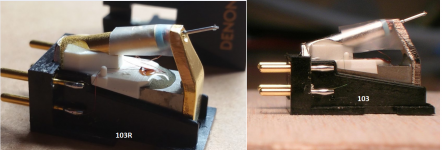
I thought I was clear it's a DL103R. There was some mention somewhere where the magnet in the new motor was incompatible with some metal platters (causing excess tracking force). This could be folklore.
Can you confirm that your LTspice sims showed SNR for this 14R source, peaked at 12mA for a Duraglit with a single ZTX851/951 pair?
What rbb' & load did you assume?
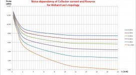
This plot best shows what I was talking about. This is the ratio of total output noise to the contribution from Rsource alone. The variable is the self bias resistor which is setting the bias current. The current is not a linear function of bias R but it is monotonic so that does not matter. 2.8K on the plot is 12mA bias, the plot only turns up because the bias resistors are in parallel with the load (500R) and increase its reflected to input noise so in fact there is not really a minimum it just keeps going down. RB = 2 Ohms.
Attachments
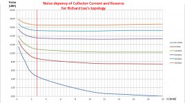
To check my formula in #541 for Richard Lee's topology, the so called Duraglit, I used LTSpice to cover a range from 0.2mA to 20 mA and for Rs from 0.1 Ohm to 40 Ohm.
All errors compared to my Formula that simply takes the Sqrt(input noise at 0.1 Ohm^2 + noise of Rs^2), where between 0 and 1dB with an average of 0.5dB.
So I see no real reason to make the formula much more complex.
Result is made visible in the graph below.
The vertical red line is for the standard 2.77mA version.
The relative point at Ic=20mA and Rs=0.1 Ohm is set at 0dBR
Above 12mA, all curves are either flat, or even worsening, exactly what Scott already figured out.
For Rs = 20 Ohm or higher Ohmic values, Ic=3mA will be enough.
For a 5R Cart, there is 1.2dB to be gained in S/N when going from 2.77 to 12mA.
For a 10R Cart 0.8dB can be gained the same way.
Hans
Attachments
I tried replacing the resistors with current sources and that makes the effect even more obvious and the plot is now the noise factor vs current directly with the effective load now constant.
Going from 2.7 mA to 12 mA to gain 2 dB is not worth it in my book since I think you would struggle to hear 2 dB or it would not be blatantly obvious anyway.
Last edited:
To check my formula in #541 for Richard Lee's topology, the so called Duraglit, I used LTSpice to cover a range from 0.2mA to 20 mA and for Rs from 0.1 Ohm to 40 Ohm.
All errors compared to my Formula that simply takes the Sqrt(input noise at 0.1 Ohm^2 + noise of Rs^2), where between 0 and 1dB with an average of 0.5dB.
So I see no real reason to make the formula much more complex.
Result is made visible in the graph below.
The vertical red line is for the standard 2.77mA version.
The relative point at Ic=20mA and Rs=0.1 Ohm is set at 0dBR
Above 12mA, all curves are either flat, or even worsening, exactly what Scott already figured out.
For Rs = 20 Ohm or higher Ohmic values, Ic=3mA will be enough.
For a 5R Cart, there is 1.2dB to be gained in S/N when going from 2.77 to 12mA.
For a 10R Cart 0.8dB can be gained the same way.
Problem with my bad eyes, or is it that for Rs=40ohm there is a minimum in noise at about 5mA? That would be surprising in this very simple model.
I thought I was clear it's a DL103R.
My apologies. You are right. I had to read back posts (8th July)
There was some mention somewhere where the magnet in the new motor was incompatible with some metal platters (causing excess tracking force). This could be folklore
Magnetics seem to be not very different between 103 and 103R if at all.
I have tested the influence of a healthy steel plate on the VTF of a DL-103.
When the lower side of the body is 2mm from the steel plate, the VTF is increased by 0.5grams.
When the lower side of the body is 3mm from the steel plate, the VTF is increased by 0.1grams.
Vinyl disk thickness + cartridge body clearance from the vinyl surface is greater than 3mm.
Add the thickness of the platter mat
George
Attachments
Denon naming conventions seemed designed to keep us all confused. See Denon - Cartridge Database - Vinyl Engine= just for the 103 series. They differ not only in coil resistance and output level, but also contilever, stylus, coil materials, magnet type, and generator geometry (the 103M is really not like other 103's).
DL103 40R 0.3mV
DL103 Gold 40R 0.3mV
DL103 Pro 38R 0.35mV
DL103 SL 14R 0.25mV
DL103 C1 14R 0.25mV
DL103 D 33R 0.25mV
DL103 FL 30R 0.28mV
DL103 GL 40R 0.25mV
DL103 LC 13R 0.25mV
DL103 LCII 13R 0.25mV
DL103 M 40R 0.12mV
DL103 R 14R 0.25mV
DL103 R/T 14R 0.25mV
DL103 S 40R 0.3mV
DL103 SA 14R 0.25mV
DL103 U 40R 0.3mV
Probably some missing.
Nothing wrong with your eyes, here is the magnified graph for just Rs = 40 OhmProblem with my bad eyes, or is it that for Rs=40ohm there is a minimum in noise at about 5mA? That would be surprising in this very simple model.
Hans
Attachments
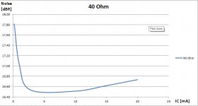
Nothing wrong with your eyes, here is the magnified graph for just Rs = 40 Ohm
So what is on the Y axis?
Denon naming conventions seemed designed to keep us all confused. See Denon - Cartridge Database - Vinyl Engine= just for the 103 series.
Thanks nezbleu for the compilation.
VE should update their price information.
When I bought mine it was 120Euro. Now it is more than double (I don’t see the point)
George
Doing the same graph from 1 Ohm to 5 Ohm for Rcart , it is still obvious that going beyond 12 mA does nor bring very much benefit.
But for a 1 Ohm cart, going from the original 2.77mA to 12 mA means an improvement of 3.2dB in S/N.
In this range from 1 to 5 Ohm, difference between LTSpice and my Formula is almost within +/- 0.1dB.
At 12 mA, noise at 0.1 Ohm is 148nV/rtHz and with Rsource 1 Ohm 2.3dB more, or 193nV/rtHz.
Not that bad at all !
Hans
Attachments
the Y axis is as explained in the text the relative noise production, where noise at Rs = 0.1 Ohm and Ic =20 mA is set as a relative 0dB point.So what is on the Y axis?
So for 40 Ohm, S/N at 5 mA is 0.25dB less as it is at 20mA.
Hans
the Y axis is as explained in the text the relative noise production, where noise at Rs = 0.1 Ohm and Ic =20 mA is set as a relative 0dB point.
So for 40 Ohm, S/N at 5 mA is 0.25dB less as it is at 20mA.
I'm missing something obvious here, I don't understand the relationship between the relative noise on the Y axis and the S/N
Magnetics seem to be not very different between 103 and 103R if at all.
I suspect folklore on that.
I'm missing something obvious here, I don't understand the relationship between the relative noise on the Y axis and the S/N
In #632 this relation is made available.
0.7dBR = 148nV/rtHz (Ic =12 mA and Rs = 0.1 Ohm)
When noise goes up by X dB, S/N goes down with the same X dB for a given Cart.
I hope this answers your question ?
Hans
Last edited:
In #632 this relation is made available.
0.7dBR = 148nV/rtHz (Ic =12 mA).
I hope this answers your question ?
But the output signal also depends on Ic, isn't it? So one cannot really divide the Y axis to a constant number to get the S/N ratio, right?
I think I may not have explained it well enough.But the output signal also depends on Ic, isn't it? So one cannot really divide the Y axis to a constant number to get the S/N ratio, right?
Output signal or gain depends on Ic, that's correct.
But in the noise calculation I have divided the output noise by the gain, to get the circuits input noise independent of gain.
I could have adjusted gain in all situations to the same amount by changing the output resistor, but for the few situations I tried to do this, it had marginally effect on the input noise, so I left the output resistor the same for all cases.
If you are convinced that this could introduce a significant error, I'm willing to redo the graphs.
But now coming back to the question concerning relation between Y axis and S/N.
For a given Cart with a certain certain Rs, the graph shows a relative noise change of X dB when changing Ic.
The S/N for this given Cart will then change by -X dB for this change in Ic.
As mentioned as an example, when going with a 40 Ohm Cart from 5 mA to 20 mA, S/N will become 0.25 dB worse independent of Vout at 5cm/sec@1KHz.
When for a 1 Ohm Cart going from 2.77mA to 12 mA, S/N will improve by 3.2dB again inpendent of Vout at 5cm/sec@1KHz.
Hans
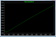
Please excuse me Guru Wurcer but I need to ask, "Do these curves take into account the varying gain with Ic due to 1/gm mutual conductance & input Z?"This plot best shows what I was talking about. This is the ratio of total output noise to the contribution from Rsource alone. The variable is the self bias resistor which is setting the bias current. The current is not a linear function of bias R but it is monotonic so that does not matter. 2.8K on the plot is 12mA bias, the plot only turns up because the bias resistors are in parallel with the load (500R) and increase its reflected to input noise so in fact there is not really a minimum it just keeps going down. RB = 2 Ohms.
The gain has an asymptope when 1/gm is so small that Duraglit simply acts like a virtual earth and shoves the input current into the load resistor.
________________
Circa 1980, taking the gain into account bla bla, I noticed the S/N leveling-off at about 3mA with the Hitachi LN BJTs. rbb' about 5R. I don't think I tested beyond the point when Env stopped dropping with my Jurassic but then SOTA measuring gear.
I got my 5mA level-off for ZTX851/951 from Waynes and H&H's data but I was ASSuming Duraglit behaved like a common or garden common-base. syn08 & Guru Wurcer say it is a lot better .. at least in SPICE world 😱
I'm not sure I conducted the real life exercise for the Rohm, Toshiba & other Olde Unobtainium Shoppe devices which had rbb' rather more than 2R. A cryptic note from that period says "Current doesn’t need adjusting for rbb’ "
Duraglit was still the lowest noise MC headamp in the known Universe until well into this Millenium so I thought taking more than 3mA from a C-cell would give more aggro (3 mth battery life) than benefit. I'm likely to keep this recommendation for the battery version ... but may raise the limit when the Solar Cell is fully validated with Duraglit 🙂
Last edited:
Please excuse me Guru Wurcer but I need to ask, "Do these curves take into account the varying gain with Ic due to 1/gm mutual conductance & input Z?"
This does not matter the noise as a ratio normalizes out. All the noise contributions see the gain when referred to input. The actual gain only matters when you are worried about gain structure, in any case here the gain varies very little past a certain Ic but the noise ratio (or whatever you want to call it, noise figure is wrong here) keeps going down.
- Home
- Source & Line
- Analogue Source
- Richard Lee's Ultra low Noise MC Head Amp