Did you replace the drivers in the hot supply with the BD140?
It pulling 1.5amps. And fets gets very hot with in seconds.
How does the base drive on the hot/cold FET driver look?
It looking same like fet gate. Both pnp has same waveform on its base.
Attachments
What's the resistance to the primary ground from the following points on the two banks?
gate of FET?
pin 9/10 of the 494?
emitter of PNP driver?
gate of FET?
pin 9/10 of the 494?
emitter of PNP driver?
What's the resistance to the primary ground from the following points on the two banks?
gate of FET?
pin 9/10 of the 494?
emitter of PNP driver?
Gate of fet = 94.7kohms all fet gates same.
Pin 9/ 10 = 0.983kohms
Emitter of pnp = 94.6kohms both pnp same
Add a resistor of about 470 ohms connected from the emitter to the collector of each of the drivers.
Add a resistor of about 470 ohms connected from the emitter to the collector of each of the drivers.
I added 510ohms on emitter to collector the current pull reduces from 1.6amp to 1amp but still all the fets getting hot in few seconds.
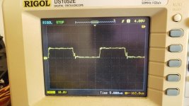
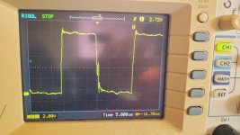
What does the waveform look like?
Waveform attached.
Attachments
Did you install all of the FETs?
Are all in that bank heating up?
When posting an image of a waveform, use the lowest vertical amp setting that will allow the waveform to fit, vertically. When compressed, it's much harder to see what's actually there.
Are all in that bank heating up?
When posting an image of a waveform, use the lowest vertical amp setting that will allow the waveform to fit, vertically. When compressed, it's much harder to see what's actually there.
Did you install all of the FETs?
Are all in that bank heating up?
When posting an image of a waveform, use the lowest vertical amp setting that will allow the waveform to fit, vertically. When compressed, it's much harder to see what's actually there.
Did you install all of the FETs?
Are all in that bank heating up?
When posting an image of a waveform, use the lowest vertical amp setting that will allow the waveform to fit, vertically. When compressed, it's much harder to see what's actually there.
Yes all the fets in place. Both side fets of both banks getting hot. Current keep increasing as they gets hot.
Attachments
You'll need to power up through a limiter, initially, for the following. This assumes that there is a resistor (10k?) between pin 4 and ground at this time.
On the 494, connect a 510 ohm resistor between pins 4 and 7. Connect a 10k resistor between pin 14 and 4.
Do the FETs heat up through the limiter?
If all seems to be OK, power up without the limiter to see if the idle current has changed.
On the 494, connect a 510 ohm resistor between pins 4 and 7. Connect a 10k resistor between pin 14 and 4.
Do the FETs heat up through the limiter?
If all seems to be OK, power up without the limiter to see if the idle current has changed.
You'll need to power up through a limiter, initially, for the following. This assumes that there is a resistor (10k?) between pin 4 and ground at this time.
On the 494, connect a 510 ohm resistor between pins 4 and 7. Connect a 10k resistor between pin 14 and 4.
Do the FETs heat up through the limiter?
If all seems to be OK, power up without the limiter to see if the idle current has changed.
Yes idle current is now only 0.4ohms. So what is all this problem is about? No fets seems to be hot again.
It appears that the drivers cannot pull down the gates of all of the FETs efficiently.
What you did was increase the deadtime. The voltage divider formed by the 510 and 10k resistors set the voltage on pin 4 slightly above 0v. If you use this as a solution, the resistors chosen need to be able to get the voltage on pin 4 to just slightly above the point where the current draw drops off.
If you're going to remove the resistors between the collector and emitter of the driver, remove them, then adjust the deadtime to the final value.
It appears that the drivers cannot pull down the gates of all of the FETs efficiently.
What you did was increase the deadtime. The voltage divider formed by the 510 and 10k resistors set the voltage on pin 4 slightly above 0v. If you use this as a solution, the resistors chosen need to be able to get the voltage on pin 4 to just slightly above the point where the current draw drops off.
If you're going to remove the resistors between the collector and emitter of the driver, remove them, then adjust the deadtime to the final value.
I removed the resistors from drivers emitter and collector. And tried with the same 510ohms and 10kohms divider and it idling on 0.4ohms. So I will leave it just so. Voltage on pin4 is only 0.2v. Also when i got the amp the rail capacitors of one bank were bulged. I changed them.
It appears that the drivers cannot pull down the gates of all of the FETs efficiently.
What you did was increase the deadtime. The voltage divider formed by the 510 and 10k resistors set the voltage on pin 4 slightly above 0v. If you use this as a solution, the resistors chosen need to be able to get the voltage on pin 4 to just slightly above the point where the current draw drops off.
If you're going to remove the resistors between the collector and emitter of the driver, remove them, then adjust the deadtime to the final value.
Do I have to change gate resistors to 100ohms or leave it 47ohms?
If you're using the 3205s, I'd leave the 47s. If everything is working properly, there's no point in changing anything.
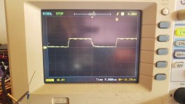
What'a the duty cycle at the output of the 494? Post an image of both pins 9 and 10 at the same time (two probes, two channels of the scope). I'd like to see that the 0.2v isn't pulling the duty cycle back too far.
What'a the duty cycle at the output of the 494? Post an image of both pins 9 and 10 at the same time (two probes, two channels of the scope). I'd like to see that the 0.2v isn't pulling the duty cycle back too far.
If you're using the 3205s, I'd leave the 47s. If everything is working properly, there's no point in changing anything.
What'a the duty cycle at the output of the 494? Post an image of both pins 9 and 10 at the same time (two probes, two channels of the scope). I'd like to see that the 0.2v isn't pulling the duty cycle back too far.
it was using IRFZ44N. amp blew power supply fets. again gate frequency gone high. and right now no mosfets and no rectifiers and TL494 alone oscillating at 63khz and i changed to TL595 and it is oscillating about 300khz. dont know whats going on with this amplifier. something must be bad which i am not seeing.
- Status
- Not open for further replies.
- Home
- General Interest
- Car Audio
- Powerbass asa 700.5