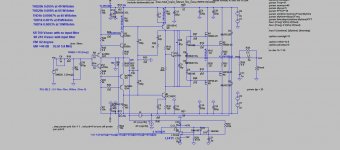
There is one interesting possibility to change a bit THD and harmonic shape at high frequencies, at 20kHz, by changing value of R20, the two pole compensation resistor.
Original value is 1k5 but could be lowered down to 220R and THD20k goes down, harmonics get more euphonic. Downside is lowering the Phase Margin but still stays very stable.
This could be done wile listening and decide what is better.
Original value is 1k5 but could be lowered down to 220R and THD20k goes down, harmonics get more euphonic. Downside is lowering the Phase Margin but still stays very stable.
This could be done wile listening and decide what is better.
Last edited:
There is one interesting possibility to change a bit THD and harmonic shape at high frequencies, at 20kHz, by changing value of R20, the two pole compensation resistor.
Original value is 1k5 but could be lowered down to 220R and THD20k goes down, harmonics get more euphonic. Downside is lowering the Phase Margin but still stays very stable.
This could be done wile listening and decide what is better.
So it's true that certain compensation scheme can be used to tailor the distortion spectrum. I tend to search for the simplest compensation, which is critical for low bandwidth amplifiers, and an easy load for the driving stage.
Just curious (as in an engineering exercise for the 120 Watt BSA version) can a pair of ecx10's drive a 4 Ohm load ?
It seems based on the SOA curves probably not.
Would the output stage require an extra pair of mosfets ?
What about substituting the ecx10's for the ecw20's ?
In either case I guess the driver stage would need to be modified for the additional ecx10 or ecw20 mosfets ?
It seems based on the SOA curves probably not.
Would the output stage require an extra pair of mosfets ?
What about substituting the ecx10's for the ecw20's ?
In either case I guess the driver stage would need to be modified for the additional ecx10 or ecw20 mosfets ?
Last edited:
Just curious (as in an engineering exercise for the 120 Watt BSA version) can a pair of ecx10's drive a 4 Ohm load ?
It seems based on the SOA curves probably not.
Would the output stage require an extra pair of mosfets ?
What about substituting the ecx10's for the ecw20's ?
In either case I guess the driver stage would need to be modified for the additional ecx10 or ecw20 mosfets ?
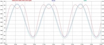
Simulation shows it can drive 4 ohm at full power.
You can use one pair of ecw20 mosfets instead two pairs of ecx10, and to use 2 pairs I am not sure yet.
http://www.exicon.info/PDFs/ecx10n20.pdf
Attachments
Thanks for the information, if I read your charts correctly then 4 ohms at 50vdc will exceed a pair of ecx10 mosfets soa curve.
For the BSA 120w amplifier to operate into a 4 ohm load it is necessary to lower the dc rail voltage.
I guess to have the BSA 120w amp capable of operating unconditionally into either a 4/8 ohm load is to add additional ecx10's albeit with a different pcb layout or substitue with a pair of the ecw20 variant which would probably require component changes in the driver stage.
Last edited:
Thanks for the information, if I read your charts correctly then 4 ohms at 50vdc will exceed a pair of ecx10 mosfets soa curve.
For the BSA 120w amplifier to operate into a 4 ohm load it is necessary to lower the dc rail voltage.
I guess to have the BSA 120w amp capable of operating unconditionally into either a 4/8 ohm load is to add additional ecx10's albeit with a different pcb layout or substitue with a pair of the ecw20 variant which would probably require component changes in the driver stage.
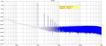
Have you looked ClassA schematic, there is +-35V of power supply?
This amp is 80W on 4ohm.
Last edited:
I've now worked out that I was looking at this from the wrong angle and interpreted the mosfet soa curves from the datasheets from a dc voltage perspective and not the ac rms voltages and thusly the current and rms power into the load or do we use the peak ac voltage and current ?
If that is the case then reduce the dc rail voltage to give 100w into 4 ohms which is plenty of power for a typical room at home 🙂
If that is the case then reduce the dc rail voltage to give 100w into 4 ohms which is plenty of power for a typical room at home 🙂
Last edited:
You can take the pre-driver stage out, stability will improve, a little higher distortion, but more music
You can take the pre-driver stage out, stability will improve, a little higher distortion, but more music
There is no predrivers and stability is very good, no need for improve.
PM=84 degree and GM=18dB.
I was wondering why use 0.27ohm wire wound R instead of MF type?
It could be used 0.22ohm or 0.27ohm wire wound or MF type.
You can take the pre-driver stage out, stability will improve, a little higher distortion, but more music
I suppose you meant without drivers, JLH did not use drivers in his 80W mosfet amp.
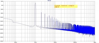
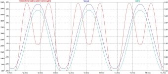
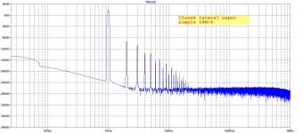
Here is this ClassA with no drivers. I increased the VAS current to cope with the mosfet drive, and here is the result.
Interestingly THD at low frequencies dropped but at high increased, specially at 4ohm load. Stability (PM and GM) did not changed, it is good as before, clipping a bit asymmetric.
Damir
Attachments
Using sPlan 7.0, ELECTRONIC-SOFTWARE-SHOP
i have export two btm, one per side.
I will try etching a two side pcb at home. 😱
i have export two btm, one per side.
I will try etching a two side pcb at home. 😱
Hello Damir,
could you please post the schematics and the BOM for the class A version (with driver)?
Best regards
Günni
could you please post the schematics and the BOM for the class A version (with driver)?
Best regards
Günni
Hello Damir,
could you please post the schematics and the BOM for the class A version (with driver)?
Best regards
Günni
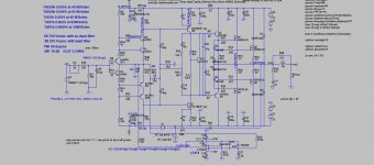
LTspice schematic is here, https://www.diyaudio.com/forums/solid-state/338814-lateral-cfa-120w-bsa-3.html#post5817929.
Latter I will prepare schematic and BOM to correspond the PCB layout.
LTspice schematic is here, https://www.diyaudio.com/forums/solid-state/338814-lateral-cfa-120w-bsa-3.html#post5817929.
Latter I will prepare schematic and BOM to correspond the PCB layout.
Thanks Damir,
take your time, since the order of PCBs (matte black) was confirmed today.
BR
Günni
Wirewound would be more rugged to temperorary overload, which might be useful.It could be used 0.22ohm or 0.27ohm wire wound or MF type.
Another (very) good amplifier.
Most difficult for newbie is deciding how to compensate the amplifier. I think all two pole compensation are clever. It can make relative simple amplifier to have very low distortion. But of course the implementation is very difficult for newbie.
Most difficult for newbie is deciding how to compensate the amplifier. I think all two pole compensation are clever. It can make relative simple amplifier to have very low distortion. But of course the implementation is very difficult for newbie.
- Home
- Amplifiers
- Solid State
- Lateral CFA 120W - BSA