Member
Joined 2009
Paid Member
with indirect heating we moved forward with power efficiency. but with linearity, several steps backward. majority of people do not care, tons of gain is fixing itNothing is funny; so called "audio tubes" were just cheap tubes in mass production. Consumer audio never was considered as more critical application than military radio and electronics, when everything was made with tubes.

Makes me imagine a HiFi quality PA system with suitable class D running subsInsanity still rules my mind in the quest for a 1KW (500 WPC) HiFi quality amp. Again I have the parts, but the output tubes will be TV sweep tubes. That one keeps inching closer to reality. I need to build it before I get too old to be capable of moving it.🙂
Cheers!
This needs basscapable speakers or headphones:
https://www.google.com/url?sa=t&sou...wwAXoECAwQEQ&usg=AOvVaw1c9XHSH1UzMajwXQkmkbDK
Member
Joined 2009
Paid Member
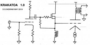
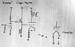
Here's the conceptual schematic. Nothing new per se, but this approach came about due to a number of considerations,
Input: I believe a simple common cathode, resistively loaded triode will help the amplifier provide a sound I will like. I'm thinking 6SL7/6H9C here.
Driver: Use of A2 grid drive needs a low impedance for +Ve grid current without the risk of blocking distortion, which favours an n-type source follower over almost any other approach. As I want to keep things simple I'm avoiding an additional negative supply rail by using choke loading which allows the Source voltage to swing negatively. Negative grid drive requires virtually zero current so there's no need for a symmetrical drive. The DCR of the choke implies that the no-signal grid voltage will be above zero depending on the standing current through the depletion MOSFET.
Output: I need the flexibility to lift the cathode above ground and I want to improve the stability and ease of setting the standing current through the output valve by reducing it's sensitivity to the standing current through the driver stage, which may have temperature variations. I've chosen to use a current sink under the cathode of the output tube. It'll need to be decoupled (not shown).
Attachments
Last edited:
Member
Joined 2009
Paid Member
Why depletion mode? Any MOSFET would work, if you provide positive bias source, with a trimmer to set the bias up. Otherwise you would need a choke with quite high DCR. A minus of constant current cathode bias is, you need decoupling, that would cause the same blocking distortions.
Member
Joined 2009
Paid Member
I was thinking that the depletion mode FET would obviate the need for this voltage supply adds components and possibly noise. The choke I have in my junk box would have a DCR of around 1k85. Am I trading off lower gm in using a depletion mode FET??
Last edited:
You are getting too low bias voltage for an output tube if to rely only on vgc of a depletion mode FET, even if it's cathode is grounded. Anyway you would need some positive bias.
Edit: I see, you added one more bias resistor in source to bias the FET. Well; it would work then, even without a positive bias source. I did not think straight, you were right. 🙂
Edit: I see, you added one more bias resistor in source to bias the FET. Well; it would work then, even without a positive bias source. I did not think straight, you were right. 🙂
Last edited:
Member
Joined 2009
Paid Member
And you were right about the cathode bias being a problem for A2 - I think I made a rookie error with that one. If I use a resistor, it'll likely be around 300R - and a decoupling capacitor. Are we then out-of-the-woods ?
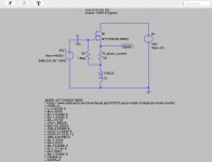
Try the IXTP01N100D or IXTP08N100D2.Has anybody here messed about with an LTspice model for depletion a mosfet ? ... distortion is rather high.
Attachments
Member
Joined 2009
Paid Member
The model works well with LTSpice XVII on WIN 7. Use standard nmos and change the prefix to X (right click on the symbol).
Hi Gareth, still having problems with the model?
Hi Gareth, still having problems with the model?
Member
Joined 2009
Paid Member
no luck I'm afraid.
see attached.
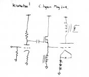
I was hoping to keep it simple and avoid a bias supply. How about fixed bias, using diodes to lift up the cathode potential without blocking distortions ?
See attached (and remember, I will have some resistors in there to self-bias the FET), the quantity of diodes depends on Vf of the diode type. I believe SY championed this approach with the 'red light district' amplifier when he used LEDs.
see attached.
A minus of constant current cathode bias is, you need decoupling, that would cause the same blocking distortions.
I was hoping to keep it simple and avoid a bias supply. How about fixed bias, using diodes to lift up the cathode potential without blocking distortions ?
See attached (and remember, I will have some resistors in there to self-bias the FET), the quantity of diodes depends on Vf of the diode type. I believe SY championed this approach with the 'red light district' amplifier when he used LEDs.
Attachments
Member
Joined 2009
Paid Member
And perhaps, another option. Filament bias using a DC filament supply. With a 4A filament supply the cathode bias resistor is going to be acceptable without bypass. But it's sure going to be toasty !!!, between 20W and 40W of magma warming heat!
With the diodes I'd only be 'wasting' ~1W.
With the diodes I'd only be 'wasting' ~1W.
Attachments
Last edited:
Member
Joined 2009
Paid Member
well it does require a few more parts and it becomes another source of noise and we have to guard against its failure so we may need additional parts to ensure the circuit doesn’t run away if the bias fails
Member
Joined 2009
Paid Member
ha! - well I may yet add a bias supply.
This project was supposed to be a quick win, a diversion on my main journey with some other projects. I wanted it kept at safe-ish voltages and simple - kind of like a 2A3 is simple. As I dig in further it gets more complicated. These transmitter tubes are a lot more trouble than I had imagined. Now that I've thrown down the gauntlet on A2 it seems I will have to impose some kind of solution.
This project was supposed to be a quick win, a diversion on my main journey with some other projects. I wanted it kept at safe-ish voltages and simple - kind of like a 2A3 is simple. As I dig in further it gets more complicated. These transmitter tubes are a lot more trouble than I had imagined. Now that I've thrown down the gauntlet on A2 it seems I will have to impose some kind of solution.
Sorry Gareth, my bad. You need Ctrl-Right-Click on the symbol to change the prefix from MN to X. Try the attached.no luck I'm afraid...
Attachments
Member
Joined 2009
Paid Member

- Home
- Amplifiers
- Tubes / Valves
- Krakatoa - venturing into A2 with SE amp