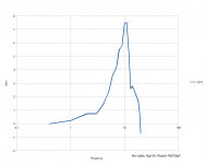
First, that's not a scope. Second, it's not a time representation of the voltage at any point on the line.JN asked how can I see it on the scope. Just according to the definition, sinus sweep and voltage measurement. As simulated for 4m of cable, inp from 0ohm, output 1Mohm load. Simulated, however scope shows the same. First signs of "sub/wavelength" effects are above 1MHz.
"Look, a squirrel" is not an option here.
Your apparent fundamental understanding of what a scope can show with respect to direction of the signal is incorrect. A scope cannot tell you which direction, so cannot tell you which is forward, which is reflected. All it can do is show the summation.
When the signal is sufficiently slow that the reflection overlaps the forward, you simply say "no reflection". That is of course, not a boundary.
What's funny, is you are fixated on the physics which is just slightly beyond your beliefs and understandings, and have completely missed the fundamentals of the entire discussion. I am reminded of a bald eagle that grabs a salmon that is too heavy for it to carry. They drown.
The bog standard t-line analysis for a 5 meter line feeding a very mismatched load is ABSOLUTELY identical to that of a multi-element LC model. As such, both models show that if you drive a step into them, maintain the same cable, but vary the load, the current at the load will climb as an exponentially decaying rate. You had one nice jpg showing the input squared, and the output climbing to value. Now vary the load but keep the rest the same, and read out the time from step input to 80% output value. You will find that it cusps when load=line.
I have told you three times now how to do this. Perhaps this time is different?
jn
we would see it for 10 kHz. If it existed. As it doesn't exist, it is a chimaera.
I'm surprised you say that. For arguments sake take the lossless case, a perfectly matched terminated source is indistinguishable from one with say 10,000 miles of cable attached. So turn the problem around now and look at the last 10m and mis-terminated load. Saying the last 10m of a long line does not behave like the rest of the line is absurd.
Perchance, for a length of rg58, what characteristic impedance would you use at 10Khz, the test frequency he used?I am looking for evidence of the necessary understanding to correctly interpret the raw data he gets from his instruments. I do not see it. I may be wrong.reasonable logic
So what is the mismatch between 100R (his nearest switch position) and 93.6 -j79.2? Somewhat greater than 1.2:1, I think. Let us take a short cable with a characteristic impedance of 93.6-j79.2, and terminate it with 100R. His bridge will tell us that there is virtually no reflection. In fact the reflection coefficient will have a magnitude of 0.38 with an angle of -72 deg. What his bridge is actually doing is telling us about the mismatch between the bridge calibration impedance and the cable termination impedance, very slightly modified by the LCR of the cable.oddly enough, he states the Zo at 10Khz (the actual measurement frequency) as 49.6 and at 1Mhz as 41.6
jn
All it can do is show the summation.
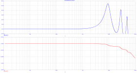
And that's it. Summation of waves at the defined point. If there are reflections at the given frequency, summation shows it. BTW, simulation and real measurement on 4m zip cord are quite in a good agreement, Rg=50ohm, Rload=1Mohm//30pF. My generator is limited to 20MHz. Frequency in the measured plot is in MHz. Gain in dB.
Attachments
Last edited:
So what is the mismatch between 100R (his nearest switch position) and 93.6 -j79.2? Somewhat greater than 1.2:1, I think.
Gamma (Zo-Zl)/(Zo+Zl) is -0.114+j*0.362 hence |G|=0.38
Load impedance module (as seen by the generator) is 122ohm
SWR is (|G|+1)/(|G|-1)=2.2
Load return loss results 8.41dB
Load mismatch attenuation results 0.68dB
Within the context of the discussion, the amp oscillates when a high capacitance cable is attached, the amp has high bandwidth, and the speaker unloads below the unity gain frequency.I have a subject line for that thread: "Faulty Power Amplifier Design."
So while we could think of the amp design as flawed, it simply was not designed to handle the capacitance of a boutique cable.
It could also have been a bad design, but that was not the context.
jn
Again, where is the separation of reflected and forward?And that's it. Summation of waves at the defined point. If there are reflections at the given frequency, summation shows it. BTW, simulation and real measurement on 4m zip cord are quite in a good agreement, Rg=50ohm, Rload=1Mohm//30pF. My generator is limited to 20MHz. Frequency in the measured plot is in MHz. Gain in dB.
You are not getting it.
jn
Gamma (Zo-Zl)/(Zo+Zl) is -0.114+j*0.362 hence |G|=0.38
Load impedance module (as seen by the generator) is 122ohm
SWR is (|G|+1)/(|G|-1)=2.2
Load return loss results 8.41dB
Load mismatch attenuation results 0.68dB
btw, since the coupler uses discrete resistors to match the cable z, we can easily change the resistor to a better value.
jn
Saying the last 10m of a long line does not behave like the rest of the line is absurd.
Last 10m of a long line driven by 10kHz wave. What will be the amplitude difference effect along those 10m? About 0.21%?
And that's it. Summation of waves at the defined point. If there are reflections at the given frequency, summation shows it. BTW, simulation and real measurement on 4m zip cord are quite in a good agreement, Rg=50ohm, Rload=1Mohm//30pF. My generator is limited to 20MHz. Frequency in the measured plot is in MHz. Gain in dB.
Takes me back to 1980. (please excuse poor copy quality)
Attachments
10kHz wave cannot "travel" in 5m of cable. Sorry. It will be the smallest portion of the wave traveling there. It will be just 5/30 000 = 1/6000 of that wave travelling in those 5m.
No need for separation. No amplitude changes in audioband (and much higher) ,means here are no reflections in this band .Again, where is the separation of reflected and forward?
🙄You are not getting it.
Last edited:
I think it would be quite difficult to design and build a directional bridge that would be able to measure reliably reflections at 10kHz. Just try to search available products. And review the principles.
I don’t see a problem with low frequencies with the bridge itself. It’s only resistors. All resistors equal to the characteristic impedance of the T-line .
The problem at low freq is with the coupling transformer which has to have Z >> Z characteristic at test frequencies (100 times higher?)
If one has a differential probe, he does not need the coupling transformer.
http://theoldcatvequipmentmuseum.or...dgeMethodofSweepFreq.ImpedenceMeasurement.pdf
George
My bad simulator MicoCap does not want to show reflections of 10kHz wave in 4m of T-Line. My bad oscilloscope does not want to show 10kHz wave reflections in a 4m of zip cord. No theory to support such thing and no publications exist. You guys still trying to get Nobel and compare this effort to discoveries of new small particles in physics? Then Bybee is serious to me, compared to this effort.
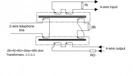
It is easy to distinguish between audio frequency signals coming and going. The original circuit used what is called a hybrid transformer. Today it is done with opamps and a balanced bridge. Yes there is some signal reflection whenever there is mismatch. Perhaps you have used a telephone and noticed what is called the sidetone or the amount of your voice that is in your handset varies. That is due to reflections from the old fashioned two wire telephone cable.
As to loudspeaker parameter shifts the DC resistance can go from 4 ohms to 16 ohms in a fully driven professional loudspeaker. Consumer grade midranges might go from 6 to 9 ohms. The inductance on a consumer midrange might go from .2 mH all the way to .4 mH. These parameters used to be monitored as the first large scale sound systems first had the ability to do so. Once the parameters were known it was much easier to set power ratings and limiters. Some gear will still shown the total impedance change.
Attached is a transformer hybrid circuit.
Attachments
Keep it real Pavel 🙂 I'm waiting for the listening test regime to be described, since that's the only thing that really matters 😉
I don’t see a problem with low frequencies with the bridge itself. It’s only resistors. All resistors equal to the characteristic impedance of the T-line .
That would be a pretty crappy bridge. Zeroing for amplitude an ordinary AC bridge does not provide enough information. In order to make any sense for measuring a reflected wave, a directional bridge needs to have the directivity and isolation much larger than the SWR intended to be measured, at and around the frequency of interest. Pretty hard to build such an animal at audio frequencies.
It is easy to distinguish between audio frequency signals coming and going. The original circuit used what is called a hybrid transformer.
Yes, that's a directional bridge and would in principle work fine, provided you could match and balance properly the transformers (to provide enough directivity and isolation). Given the magnitude of reflections we are talking here it is unlikely that could be practically done.
This is one of those things much easier to do at RF, since Baluns would provide an almost perfectly balanced transformer.
It requires only one adjustable resistor to work. You can buy the transformers off the shelf. Pretty standard circuit and usage. Used by conference call telephone folks, call in talk shows, even old fashioned computer modems.
https://catalog.triadmagnetics.com/Asset/TY-146P.pdf
- Status
- Not open for further replies.
- Home
- Member Areas
- The Lounge
- John Curl's Blowtorch preamplifier part III