OK, thanks for clarifying that. From now on, when you speak of impulses reflecting up and down a cable we can ignore it if we wish and instead think of currents flowing in an LCR model - as you say, the two models give the same results. The time delays in the impulse model become minor phase shifts in the lumped model.jneutron said:No, JN is saying they are fully equivalent (no to 1).
JN is also saying that if the change reaches into the ITD thresholds, it cannot be discounted, so possibly maybe to 2.
As Scott proved a long time ago, they are equivalent models. Anyone who glibly discount what I have been saying need only use the conventional LCR distributed model to arrive at the EXACT same results as the t-line.
So even if one doesn't agree with me, conventional analysis produces the exact same results.
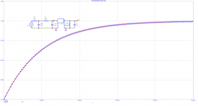
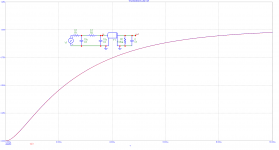
This is that interesting case that shows that with a mere single RC band limiting and ideal source we may have reflections because of the initial sudden break. This will disappear if the initial break is removed by the double RC e.g.. Or a truly band limited system. The key is the signal derivative at the beginning. Note that the difference is in R3 (0 vs. 0.1).
Attachments
Absolutely. Everybody is hung up on the t-line model I use, so the results get lost in the shuffle.OK, thanks for clarifying that. From now on, when you speak of impulses reflecting up and down a cable we can ignore it if we wish and instead think of currents flowing in an LCR model - as you say, the two models give the same results. The time delays in the impulse model become minor phase shifts in the lumped model.
The math is simpler with the t-line, I don't have to take my shoes off to do calculations.
If I am given a cable with an L and C per foot number, I can tell how it will respond to specific loads without doing an extensive simulation, or even just the LCR math. If I want to reduce the load dependent interaction with the cable, I just halve the cable z (sqr(L/C)) or model classically the L/C/R response..
And selection of zobel becomes trivial as well..
Ah, "time delays become minor phase shifts..."
Humans can discern an interaural time shift of 2uSec interchannel. Do we consider 2 uSec minor and not discernable? Way back in the past, I certainly would have. But I learned stuff in the intervening years, and read the research papers showing the test results. I was quite amazed at the single digit microsecond capability of humans..who would have thought?
jn
Last edited:
Big diameter pair, each made of very thin individual twisted wires of oxygen free copper (D=3mm, between 9 & 8 AWG), shielded by this kind of thing:How did you do this shielding ?....coaxial/triaxial or shielded pair cable ?.....driver baskets grounded ?.....compensation networks across drivers or box input terminals ? etc , I'm interested to know what you have done and what you found please.
Gaine de protection / tressee / pour cables / de cables electriques - B-CU 156 - NORRES Schlauchtechnik GmbH and covered by a plastic braid.
Connected to the ground speaker output, amp side, and the chassis of the speaker the other side. (no current across)
What I have found ? Nothing. No visible or audible difference, appart a slight phase turn at HF (out of the audio range) due to the increased capacitance.
It was a try (i'm curious), I will not not redo-it. But, well, I have them.
So. is the back/counter emf from the loudspeaker reduced if I place a low value resister at the speaker (across it)? Not an RC network.... just an R.
And, 2; By reducing the range of Z variation as a load on the PA, is this audible with some amp topologies more than others'?
THx-RNMarsh
And, 2; By reducing the range of Z variation as a load on the PA, is this audible with some amp topologies more than others'?
THx-RNMarsh
Last edited:
Thanks. I didn't go through the article entirely, but wonder where he got the test frequency of 1786 hz from.😕
The pages I'm holding in my hand are from one of his writeups I do not see in those links..part 2..
In his paper cable, amp, and speaker interactions part 2, he has appendix 2 which details the construction of a two transformer dual directional coupler with a directivity of 53 dB at 1Khz, and isolation of 30dB.
jn
If I were discussing amplitude change along the cable, your comment would be relevant and correct.6km wave on a 6m cable will make 0.6% amplitude difference along the cable. 6km wave is 50kHz speaking in frequencies. Is it important?
However, I am not talking about that. You still do not get it..
jn
Last edited:
Never tried an R (Have mercy on the amp !), but, better a RLC at resonant frequency.So. is the back/counter emf from the loudspeaker reduced if I place a low value resister at the speaker (across it)? Not an RC network.... just an R.
And, 2; By reducing the range of Z variation as a load on the PA, is this audible with some amp topologoes?
Yes, it is audible. And, measuring the response curve at the speakers terminals (after speaker's cables and passive filters if any), a visible difference in the response curve.
On the subjective point of view, basses more dried, low medium less invading: male voices are more natural.
It is easy to do by simple calculations, looking at the impedance curve of the speaker in free air.
Strangely, it will work as well once in a bass reflex. Just you need sometimes a little adjustment of the R if it goes under the DC resistance at the resonant frequency of the box. (To make a long story short, it change the Thiel and small parameters).
While we are on this, a RC to compensate the coil inductance, and you get a flat impedance curve. There, you got smoother treeble. Less aggressive, more fluid. (female voices will thank-you)
i do-it on all my speakers and consider those networks as part of them.
Now, I run to shelter myself from the cannonballs.
Last edited:
So. is the back/counter emf from the loudspeaker reduced if I place a low value resister at the speaker (across it)? Not an RC network.... just an R.
And, 2; By reducing the range of Z variation as a load on the PA, is this audible with some amp topologies more than others'?
THx-RNMarsh
The resistor damps possible RF EMI reflections, bundles of impulses. It is measurable with the scope. Make it as cable Zw. The cable is then end terminated.
Useful knowledge and insights for running audio business. Have you seen his posts on other forums?Some people seem to have an unusually sensitive obfuscation detector. Can make it easier than otherwise to result in some false positives. Might be worth considering dialing back the sensitivity a little in Jakob2's case. Some useful knowledge and insights might benefit everyone here, not just you.
As Scott proved a long time ago, they are equivalent models. Anyone who glibly discount what I have been saying need only use the conventional LCR distributed model to arrive at the EXACT same results as the t-line.
So even if one doesn't agree with me, conventional analysis produces the exact same results.
Maybe someone can find the posts, there were pictures. IIRC I took 10m of cable and 100 steps (~500ps) each. We need the L, R, and C per foot (G is ignored), with all due respect to DF96 we do not need the characteristic impedance at audio frequencies from the telegraphers equation to build the model. The propagation velocity gives e/e0 (mu = mu0 is assumed). As I posted a day or so ago you only need to measure C and the propagation velocity.
Comparing the lumped model to the distributed model in SPICE the results were exactly the same, with the distributed model looking like a sampled version of the lumped model at 1ns steps (the back and forth transit time), even Nyquist is happy. As an aside it think there is even a verification of the sampling theorem buried here, quantising the length of the t-line is equivalent to quantising time.
The point is you get the step response and hence the impulse response of a linear time invariant system so it has to be the same answer no matter how you do it. I think jn is concerned that a real speaker is neither linear nor time invariant in many cases.
Last edited:
And yet, it's not often.even Nyquist is happy.
Especially when he bet with Murphy.
A loudspeaker is nothing that can be expected of a civilized gear.I think jn is concerned that a real speaker is neither linear nor time invariant in many cases.
Last edited:
Please keep posting. There are silent readers learning these things. If not now, they will later because these subjects appear when searching online.Many people here do not understand this simple fact. Maybe for the reason they have no educational and experimental background in this field. Jan started a good thread
https://www.diyaudio.com/forums/the-lounge/338453-ignorance-resource-new-post.html
I think that ignorance is the main reason why threads like this one (JC BT part XY) may exist. Every attempt for explanations is completely useless, then. Wasting time.

I somehow can't imagine him pushing a particular product on anyone 😕🙂Useful knowledge and insights for running audio business. Have you seen his posts on other forums?
What real world mechanism ultimately is? From here Perception Lecture Notes: Frequency Tuning and Pitch PerceptionI think jn is concerned that a real speaker is neither linear nor time invariant in many cases.
"von Békésy used linear systems theory and Fourier analysis to characterize the motion of the basilar membrane. He found that the basilar membrance acts as a shift invariant linear system (by testing shift-invariance, the scalar rule, and superposition). He then used sinusoidal stimuli (pure tones) to measure the frequency response at different points along the basilar membrane. He then was able (using linear systems theory) to predict the response (that is, the motion of the basilar membrane) for any sound."
And after this point, I'm in over my head.
You do appear to be.
I do realize that transmission lines only exist at multiples of wavelength...
That is incorrect. They are ubiquitous, but often negligible for audio.
If he did, it would make things too obvious and Mark would have smelled a rat. 😉I somehow can't imagine him pushing a particular product on anyone 😕🙂
I speak about BW limited system as audio is and I am saying there are no reflections if signal components at the cable input have all wavelengths in orders longer than is the cable length.
There are always reflections. Maybe think about it this way: suppose you have a 24-bit dac with no output filtering so that tiny steps are produced. Obviously, the steps can reflect from the other end of a cable since they have RF frequency components in the step edges. Even if the steps are so tiny in amplitude the are buried in noise, they are still there and can still reflect. So, what is the limiting case if we make the steps smaller and smaller? We just end up with a Smith Chart type of view of the reflections. If a cable is very short compared to signal wavelength, it still takes finite time for an infinitesimal signal change at the source to propagate down a cable (or other TL structure) and either be absorbed or reflected at the load end. Now, maybe someone wants to define reflection to refer to some other effect, but to me an infinitesimal reflection is still a reflection.
And what impedance compensation ?.Big diameter pair, each made of very thin individual twisted wires of oxygen free copper (D=3mm, between 9 & 8 AWG), shielded by this kind of thing:
Gaine de protection / tressee / pour cables / de cables electriques - B-CU 156 - NORRES Schlauchtechnik GmbH and covered by a plastic braid.
Connected to the ground speaker output, amp side, and the chassis of the speaker the other side. (no current across)
What I have found ? Nothing. No visible or audible difference, appart a slight phase turn at HF (out of the audio range) due to the increased capacitance.
It was a try (i'm curious), I will not not redo-it. But, well, I have them.
- Status
- Not open for further replies.
- Home
- Member Areas
- The Lounge
- John Curl's Blowtorch preamplifier part III