OK thanks.
I didn't thought shorting input as it grounded with a 100k resistor but you're right, shorting ensures no input noise.
Thanks a lot for your reply.
Best regards.
I didn't thought shorting input as it grounded with a 100k resistor but you're right, shorting ensures no input noise.
Thanks a lot for your reply.
Best regards.
hi
I adjusted bias my on mx50se pair to 5.1mV, it's close to 17mA each.
i didn't thought a 2.2k trimmer had to be so precisely adjusted.
ambient temperature is another thing to do with, a simple breath or a finger on heatsink make bias fluctuate a bit.
for better ease I can recommend using a 820R + 470R trimmer instead of 2k trimmer. don't forget to adjust to 1k serial before soldering.
I seen bias can be higher, some sellers seems to set it to 30ma, i'll give a try when it will plays music.
Hi All, im using my MX50SE with LJM NAC42.5 clone preamplifier, i did small modification on preamp, so far sound nice, next plan to build another MX50SE for biamping my speaker. I recommend to try this preamplifier with MX50SE!!!!
Hello friends, I have two pairs of 2SA1943 / 2SC5200, I want to replace the KTB817, KTD1047, by Toshiba. It's possible? What is needed to make the exchange?
I wanted to make the exchange because one of the amplifiers goes into sealing first than the other, as the toshibas are stronger I imagined that this scenario could change. Another question is which gain resistor is advisable? 330R or 470R? I'm sorry for my questions, I'm not a professional, just a hobbyist.
If you use 470R resistor amp will have lower gain and it shall be more suited for use with proper preamplifier. With 330R which is supplied with the kit the gain will be higher but not much higher. If you use amp with PC sound card, the card is itself preamplifier and you don't need any other preamplifier.
What could I do to earn more bass in the sound? I feel that the amplifier has a dry beat without the bass vibration
Hello friends, I have two pairs of 2SA1943 / 2SC5200, I want to replace the KTB817, KTD1047, by Toshiba. It's possible? What is needed to make the exchange?
do as ivanlukic told you - just solder your replacement. I also use
2SA1943/2SC5200 pair in my MX50SE, it works perfectly!
alisson6101, perhaps you can try replacing input 3.3uf cap with a 10uf one.
You can find some decent quality "cbb 106j" on bay or Ali and tell us.
You can find some decent quality "cbb 106j" on bay or Ali and tell us.
help with phase / grounding issue on LJM MX50SE
I'm wondering if anyone has any ideas relating to my MX50SE build. Both boards were pre-assembled so are presumably identical. I've checked my wiring repeatedly and have things grounded properly (star model). However, my outputs seem to be out of phase with one another. I get far better bass response when connecting one speaker with reverse polarity - the usual low-tech verification. (B&W speakers - definitely wired properly internally and verified by other DIY speakers) But, for what it's worth, I notice wider separation/imaging when the speakers are connected 'properly' (red-red, black-black). My guesses are that:
1) somehow the circuit boards were incorrectly factory-assembled... seems unlikely though
2) my adjustable power supply board, which accepts an AC or DC feed, outputs slightly different DC+ and DC– voltages against ground, even when both adjustment screws are 'wide open'
3) I need discrete power supply boards - one for L and R channels - rather than powering both amp boards in parallel
4) upcycling a 20v DC Apple laptop power source (the old yo-yo version) is not such a hot idea. Also, I'm grounding MAG straight to the AC receptacle, not the shielded strand from laptop PSU.
Any hypotheses or recommendations - for diagnosis or repair - would be greatly appreciated!
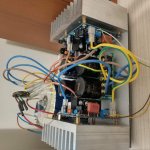
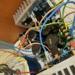
... the build otherwise turned out great. I used a spare, very compact polished stainless steel junction box, which also serves as an effective outer heat sink, with aluminum slabs internally between it and the output transistors. Photos to come.
I'm wondering if anyone has any ideas relating to my MX50SE build. Both boards were pre-assembled so are presumably identical. I've checked my wiring repeatedly and have things grounded properly (star model). However, my outputs seem to be out of phase with one another. I get far better bass response when connecting one speaker with reverse polarity - the usual low-tech verification. (B&W speakers - definitely wired properly internally and verified by other DIY speakers) But, for what it's worth, I notice wider separation/imaging when the speakers are connected 'properly' (red-red, black-black). My guesses are that:
1) somehow the circuit boards were incorrectly factory-assembled... seems unlikely though
2) my adjustable power supply board, which accepts an AC or DC feed, outputs slightly different DC+ and DC– voltages against ground, even when both adjustment screws are 'wide open'
3) I need discrete power supply boards - one for L and R channels - rather than powering both amp boards in parallel
4) upcycling a 20v DC Apple laptop power source (the old yo-yo version) is not such a hot idea. Also, I'm grounding MAG straight to the AC receptacle, not the shielded strand from laptop PSU.
Any hypotheses or recommendations - for diagnosis or repair - would be greatly appreciated!
... the build otherwise turned out great. I used a spare, very compact polished stainless steel junction box, which also serves as an effective outer heat sink, with aluminum slabs internally between it and the output transistors. Photos to come.
Hi,
1) Unlikely, if they were build the wrong way, they most likely wouldn't work at all.
2) How much is "slightly different"? A few milivolts is no problem, but several volts can become a problem. Do you have any DC-offset on the output ? (more than +-50mV).
3) No, you don't need one power supply for each amp. They will work just fine in parallel, as long as the power supply has enough power.
4) Depending on how you did it, this one could be a problem. Do you use 2 mac chargers in series ? Do you use 1 charger with voltage multipliers, and then split it into a dual voltage ?
I strongly recommend not using any special "trickery", when building power supplies for power amps. The simplest way, is usually the best for DIY use. So find yourself a dual winding transformer with 2x25VAC (2x20VAC is fine too) and 160-300VA, and attach that to a rectifier bridge and a couple of caps (somewhere between 2x8200-2x15000uF minimum 50Volts rating).
Alternatively, if you insist on using switchmode, then you need to get one that is made for the purpose. You can get 2x30V 6 to 10 amps, if you search the web.
In theory, if you had 2 Mac chargers in series it could work, but I'm not sure if they have big enough peak current. Chargers are made for delievering a steady stream, and not sudden peaks. But I'm no expert on switch mode power supplies. If they are made properly, they work just fine. But from my experience, computer chargers are made as cheaply as possible, so don't expect any superior performance.
Hello! Tell me, please, what power should be the transformer for this amplifier? 200 watts enough for two channels?
And what voltage and current of the secondary windings of the transformer will be optimal for this amplifier? In general, the voltage of the secondary windings depends on the connected load on the output of the amplifier?
I have speakers from the LG music center. They are 100 watts and 6 ohms.
Now the amplifier is powered by a transformer with a voltage of 2 * 18 V. Can it be worth increasing this voltage? Thanks for the answer!
Hi guys I’m new to diy amp projects I built a few very easy velleman little amps which worked really well now I have bought this mx 50 and was wondering what else I need to buy to make this work . Please help !! Would love some ideas I’m good at soldering but that’s as far as it goes . I’m learning as a go and I am loving every minute of it thank you in advance for any input.
Hi, can i replace the 10k input impedance and the 10k gain resistor which is the big one with 33k resistors?
Based on the statement that Zin must be at least 5 to 10 time higher than Zout ,yes 1k seem to be a good choice.
A bit unusual value though.
is it a good idea to increase 10k input impedance resistor to 47k to use 50k volume pot? and what would be the consequences?
I can't tell you.
It probably plays a role in noise input, stability and perhaps bias stability.
You ça try and tell us
It probably plays a role in noise input, stability and perhaps bias stability.
You ça try and tell us
is it a good idea to increase 10k input impedance resistor to 47k to use 50k volume pot? and what would be the consequences?
There is no need to do this.
In any case, ideally you should have a buffer or a preamp with a small amount of gain (x2 or so) between the output of the pot and the input of the amplifier, as the MX50 has an input filter (R14 / C7), which means a pot with it's varying output impedance will act as a variable HF filter when connected directly to the amp.
Additionally R18 and R15 are both 10k to maintain DC balance, so if you change R18 to 47k you will upset the DC balance.
Component values given are ref this post.
Last edited:
- Home
- Amplifiers
- Solid State
- LJM MX50 kit amp