hello,
I am new on this forum and I feel completely shocked, discovering that some people simply do not understand the foundations of this compact power amplifier published by Elektor.
There is a vast litterature, including patents taken by Comlinear (National Semi), clearly showing what makes a CFB amplifier, and the associated advantages and features.
No doubt the compact power amplifier published by Elektor is a CFB one. The CFB concept is something one should learn and understand before publicly writing "this Elektor design takes a sample of the output voltage, then returns it to the inverting input, so describing a voltage feedback amplifier". This is not semantic. This is plain ignorance.
More acceptable arguments would be : "Come on, all those old preamplifiers and amplifiers dating back from before the advent of the long tailed input pair, with the global feedback applied on the emitter of the input transistor, can we say they all were CFB designs ?" "Is symmetry mandatory ?"
Apart from the CFB feature, the use of IGBTs in a complementary feedback pair (CFP) providing some voltage gain is quite unusual. However it is not the first time Elektor is publishing IGBTs in a complementary feedback pair (CFP) :
- article number #950077 (June 1995) - 90 Watt IGBT power amp (+ and -43V supply, voltage feedback, differential input, fully symmetric, no cascodes), plus an interesting appendix about IGBTs in general (June 1995 also)
- article number #960049 (March 1996) - subwoofer amplifier (+ and -49V supply, voltage feedback using an AD847 op-amp as input, two IGBTs in parallel, 245W on a 4 Ohm load)
I now have a three questions :
- Come on, all those old preamplifiers and amplifiers dating back from before the advent of the long tailed input pair, with the global feedback applied on the emitter of the input transistor, can we say they all were CFB designs ? Is symmetry mandatory ? Should we call all those old designs "asymetric CFB" ?
- what is the Elektor article number so I can search the Elektor database and possibly download the pdf of the article of the Elektor compact power amplifier ?
- can somebody provide a link to the followup Elektor seems to have published ?
thanks
This amplifier uses current feedback amplifier as opposed to voltage feedback.
People are confusing 'current sense feedback' (which of course is perfectly acheivable with a voltage feedback topology amplifier) with 'current feedback topology'. Two totally different things.
Having said that, I believe this amplifier is a risky design - you need to be experienced and competent to build one and sort it out.
Agreeing ! That's why I'm looking for any followup (possibly corrections) published by Elektor, about this particular amplifier.Having said that, I believe this amplifier is a risky design - you need to be experienced and competent to build one and sort it out.
I hate to dig up old posts again but I didn't do it this time. It is interesting to read the debate between voltage and current feedback and I don't think my input here will change anything but this is my take.
As reference I will use E.H. Nordholt's book 'Design of high performance negative feedback amplifiers'. As Jan and Marcel already alluded to, the way how the active part of the amplifier is built had no relation on the naming of the feedback (except to the marketing department of cause). When a 'current mode feedback amplifier' (purposely between quotes) is used to built a voltage amplifier, the resulting amplifier is still a voltage amplifier. The output voltage is sampled and fed back to the input thereby creating in the asymptote an amplifier with an infinite input impedance and a zero output impedance: the definition of a voltage amplifier. The so called 'open loop' (technically a wrong term) impedances of any of the in- and output ports is of no consequence, with sufficient loopgain it will create a high input and low output impedance.
Does a different kind of input stage have advantages with to respect to frequency response and compensation characteristic? Of cause it does, but that does not justify renaming a feedback topology that has been named since Blackman.
PS. Marcel, Kim here from a long time ago.
Yet another battle, this time within the feedback definition itself..
VFB and CFB mean both nothing.
The true terms should be Voltage or Current REFERENCED Feedback.
In this respect, janneman brought the good explanations.
VFB and CFB mean both nothing.
The true terms should be Voltage or Current REFERENCED Feedback.
In this respect, janneman brought the good explanations.
hi, I see your point.
To me also CFB looks like an acronym that got coined by marketers. But everybody should be happy with that. Marketers are not so stupid. Let me show you !
For people like me, a CFB amplifier means "an amplifier that loves to have his corrective current widely increasing with the error it delivers". You can't invite Blackman on this table. Leave him where he is. The most important thing about CFB is the first letter "C", like current. That is the starting point.
The deep meaning of the two letters that do follow "FB" is that yes, this structure admits feedback. And it doesn't state wheather the feedback occurs with current, voltage, or your mother. So here, let us get Blackman, on the table. And yes, a CFB amplifier is still a CFB amplifier, even if the feedback samples the output voltage, and puts a managed copy of it on the emitters of the input stage. I fully agree with you : at the end of the day, this CFB amp sees a Vbe voltage difference at his input, and that's the only thing he reads for doing his job. And feedback will increase the input impedance. Like any other amplifier subjected to negative feedback.
So, in essence, the whole point of CFB amplifiers is not about feedback, but about the vastly improved capability of the amplifier, to proportionally self-adjust in function of the error at the output, by delivering a vastly increased correction current where it is actually needed.
You need a deep understanding of the inner working of the conventional amplifiers, fitted with a long tail pair at the input, to understand what is the essence of a CFB amplifier.
In a nutshell, a conventional amplifier fitted with a long tailed pair at the input, only has a narrow way of action, never more than the quiescient current of the long tailed pair, which is less than 1 milliamp in audio (if one wants to keep low bias currents at the input), and slightly more with a dual FET at the input (say 2 or 3 milliamps). This limitation occurs in the input stage. Of course, there will be a strong current amplification from the first stage to the last stage. But with a first stage that is considerably limited, how can you expect your rocket demonstrating ultra-fast attitude changes, when the pilot is slow and lazy ? Those conventional amplifiers suffer from slow slew rates, in the order of 20V/µs which is however considered by some as sufficient for audio below 100 Watt power on 8 Ohm.
In a nutshell, CFB amplifiers get a completely different pilot, in their first stage. This pilot has an extended range of correction. He can deliver a current of 5mA even if he is biaised at 0,5mA. The trick is to get rid of the current source, as biaising source. That's very easy if you get rid of the long-tailed pair, and get the feedback on the emitter of the input transistor. With those figures, the CFB can exhibit a x5 improvement on slew rate. Slew-rates like 100V/µs are a bare minmum for CFB amplifiers. But we are not yet finished, because of asymetry.
Asymetry : wait a minute, if the input transistor is a NPN, okay, he will be able to sink a lot of current when the feedback delivers zero volt (on the emitter), while the input (on the base) gets quite positive. Then you can expect a fast and ample response. Unfortunately, the opposite cannot occur. When the feedback delivers zero volt (on the emitter), while the input (on the base) gets quite negative, the pilot cuts off, walks away, like vanishing in the nature. The whole circuit then lives on inertia, and this is not going to cause a fast and ample response. This kind of asymetry is not tolerable. That's far away from the behaviour of a strong pilot ! That's not a CFB amplifier yet !
This is the reason why all those old amplifiers and preamplifiers designs, dating back from the sixties, well before the advent of symetric designs, having their feedback on the emitter of their (sole and only) input transistor, are not CFB amplifiers. They are "half" CFB amplifiers, with heavily asymetric slew rates. One may thus observe an outstanding 50V/µs on the falling edges, and a very modest 10V/µs on rising edges.
Now, take such old fashionned pre-seventies amplifier, build another one completely symetric (NPNs become PNPs and PNPs become NPNs), couple them together, don't change the feedback network, and you will get a proper CFB amplifier ! The big issue is how to connect the two inputs together and biaising them, avoiding two separate biaising networks, capacitive coupling, and ensuring that the idle current doesn't ramp up or down with temperature.
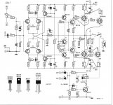
Read again Elektor schematic.
To me also CFB looks like an acronym that got coined by marketers. But everybody should be happy with that. Marketers are not so stupid. Let me show you !
For people like me, a CFB amplifier means "an amplifier that loves to have his corrective current widely increasing with the error it delivers". You can't invite Blackman on this table. Leave him where he is. The most important thing about CFB is the first letter "C", like current. That is the starting point.
The deep meaning of the two letters that do follow "FB" is that yes, this structure admits feedback. And it doesn't state wheather the feedback occurs with current, voltage, or your mother. So here, let us get Blackman, on the table. And yes, a CFB amplifier is still a CFB amplifier, even if the feedback samples the output voltage, and puts a managed copy of it on the emitters of the input stage. I fully agree with you : at the end of the day, this CFB amp sees a Vbe voltage difference at his input, and that's the only thing he reads for doing his job. And feedback will increase the input impedance. Like any other amplifier subjected to negative feedback.
So, in essence, the whole point of CFB amplifiers is not about feedback, but about the vastly improved capability of the amplifier, to proportionally self-adjust in function of the error at the output, by delivering a vastly increased correction current where it is actually needed.
You need a deep understanding of the inner working of the conventional amplifiers, fitted with a long tail pair at the input, to understand what is the essence of a CFB amplifier.
In a nutshell, a conventional amplifier fitted with a long tailed pair at the input, only has a narrow way of action, never more than the quiescient current of the long tailed pair, which is less than 1 milliamp in audio (if one wants to keep low bias currents at the input), and slightly more with a dual FET at the input (say 2 or 3 milliamps). This limitation occurs in the input stage. Of course, there will be a strong current amplification from the first stage to the last stage. But with a first stage that is considerably limited, how can you expect your rocket demonstrating ultra-fast attitude changes, when the pilot is slow and lazy ? Those conventional amplifiers suffer from slow slew rates, in the order of 20V/µs which is however considered by some as sufficient for audio below 100 Watt power on 8 Ohm.
In a nutshell, CFB amplifiers get a completely different pilot, in their first stage. This pilot has an extended range of correction. He can deliver a current of 5mA even if he is biaised at 0,5mA. The trick is to get rid of the current source, as biaising source. That's very easy if you get rid of the long-tailed pair, and get the feedback on the emitter of the input transistor. With those figures, the CFB can exhibit a x5 improvement on slew rate. Slew-rates like 100V/µs are a bare minmum for CFB amplifiers. But we are not yet finished, because of asymetry.
Asymetry : wait a minute, if the input transistor is a NPN, okay, he will be able to sink a lot of current when the feedback delivers zero volt (on the emitter), while the input (on the base) gets quite positive. Then you can expect a fast and ample response. Unfortunately, the opposite cannot occur. When the feedback delivers zero volt (on the emitter), while the input (on the base) gets quite negative, the pilot cuts off, walks away, like vanishing in the nature. The whole circuit then lives on inertia, and this is not going to cause a fast and ample response. This kind of asymetry is not tolerable. That's far away from the behaviour of a strong pilot ! That's not a CFB amplifier yet !
This is the reason why all those old amplifiers and preamplifiers designs, dating back from the sixties, well before the advent of symetric designs, having their feedback on the emitter of their (sole and only) input transistor, are not CFB amplifiers. They are "half" CFB amplifiers, with heavily asymetric slew rates. One may thus observe an outstanding 50V/µs on the falling edges, and a very modest 10V/µs on rising edges.
Now, take such old fashionned pre-seventies amplifier, build another one completely symetric (NPNs become PNPs and PNPs become NPNs), couple them together, don't change the feedback network, and you will get a proper CFB amplifier ! The big issue is how to connect the two inputs together and biaising them, avoiding two separate biaising networks, capacitive coupling, and ensuring that the idle current doesn't ramp up or down with temperature.
Read again Elektor schematic.
A low impedance inverting input imply a low impedance feedback
network as well, so there s MORE current running through the feedback path
than in a classical differential s FB path, leading some to deduct that
this is a current controlled amp.
If we were to follow this definition to determine what is a CFB, none of the
differentials op amp using Bjts at the input would qualify as VFB.
This latter defintion would then be restricted to the ones having fet s inputs.
Last edited:
Steph, I see you argument but I have to respectfully disagree.
1) The level of biasing of the input in a conventional input stage doesn't in theory have anything to do with the slew rate. Only when you take the stability into account and you use Miller-compensation to stabilize the amplifier you are going to hurt the slew-rate. The solution this is to reduce the trans-conductance of the input stage, classically done with Fets, but this can be accomplished with emitter degeneration as well. This way stability and slew rate can be decoupled and both can be optimized separately. This is why amplifiers with FET inputs usually have a better slew rate then amplifiers using a bipolar input.
2) You describe the CFB input stage essentially as a class AB stage meaning that it can source more than the bias current, contrary to a common differential pair. This is correct and it is another means to decouple the small signal stability with large signal slew rate behavior. There is however no reason not to do that for a conventional differential input pair as well. Look up US patent 6492870 for example.
In essence changing the topology of active part in a feedback amplifier will give you the ability to trade off various parameters, but it does in to way change the topology of the feedback.
Just found this old thread, and, with the benefit of hindsight, also a paper that I didn't have at the earlier time.
Interesting, to see a consistent view of the discussion: Current Feedback Myth
One interesting view on the BW conparison is that a 'VFO' is generally unity-gain compensated, so at higher gains it is excessively overcompensated. Reduce the compensation cap to match the gain, and the BW difference disappears!
Jan
To claim CFA's are a nonsense because IC vendors provide VFA devices with similar bandwidths seems to me to be missing the finer points of why we have different opamps in the first place. Settling time, overshoot, phase margin and phase fidelity etc are all parameters that are critical in applications like video buffers etc where CFA can bring benefit. In audio power amplifiers, no matter what topology you choose, you need about 60 degrees or more PM at the ULGF. CFAs, with their lower OLGs can provide this PM but at higher ULGFs, and wider LGs.
Last edited:
For anyone still playing about with this design, here is another worthwhile improvement:
The resistors from the collectors of T12 and T13 to ground are reduced to 2K2 each, so that the feedback is reduced to 24dB (from 42dB in the original design).
This makes for a very natural, effortlessly reproduced sound with a huge soundstage. Genuine hi-end material.
For some reason I got a sudden urge to tweak my amp and I thought I could try something like this.
I have the schematic but I'd like it if someone could confirm if this reduced resistor is the R28 (10k) on the board? I can't see any others on the way to ground, but I might not be that good in reading schematics...
AND: Could I first try to reduce the value to 5k with just adding another 10k on top of the other? Would that affect the feedback some bit that I might notice? If I do this, do I also need to rebias? That is the most painful task with this amp!
Thanks! I could also build another amp some time... Anything worth looking to replace this one? There's nothing wrong with this one but I'd like to try something else for change.
--Thread has been too long for me to read...
--It includes the argument inside about the type of feedback while very few can understand the principal of operation of the output stage on its own regardless the operation of feedback or the VAs or the front stage ....Similar to the output stage of the P3A that very few managed to understand why it sounds so well ...
--Like most audio Elektor circuits obviously this one also will suffer of a number of stability issues that only magic can be done to cure them
EDIT: Please replace: ""Like most audio Elektor circuits ..."" with ""Like all audio Elektor circuits ...""
--front stage like designed can and will perform good in paper but never in real life due to various tolerance issues, beta and temperature depending while the servo will only complicate things and add almost nothing to sound, sonics and quality
One that is capable with simulators ( i am not ) should create a a circuit even copy the front stage of a P3A go up to the drivers as was while add mosfet outputs CFP style. THAT WILL BE AN INTERESTING THING TO SEE
Been trying to push people with experience like Hugh to investigate that since i cannot But Hugh like most of designers is looking at the original circuit of the P3A and continue to think EFP ( like many others ) Hugh is a charming personality and a very nice man ...Talking to him and exchanging email was a treat to my soul ...still i am not sure if you can teach an old dog new tricks ...
If any one is willing to see that i will be around waiting
Kind regards
Sakis
Last edited:
Έκανα την κατασκευή το 2000 περίπου χρονικά. Έπαιξε με την πρώτη! Πολλή καλό ήχο .το ρεύμα ηρεμίας το έφερα εύκολα. Κάποια στιγμή πριν περίπου δύο κάηκε το ένα gt20d101 .Γιαυτό αποφάσισα να τον βάλω mosfet.Και συγκεκριμένα τα irfp240/irfp9240 .Το πρόβλημα ηταν οτι δεν μπορούσα να φέρω το ρεύμα ηρεμίας στο 0.Ρωταω έα ν μπορώ να αντικατάσταση το gt 20d101 μέ ενα άλλο IGBT?

English only please.
I did the construction in about 2000 chronicles. He played the first one! That's a lot of good sound. I brought the peace stream easily. Some time ago, about two burned one gt20d101. That's why I decided to put him MOSFET. And specifically the irfp240/irfp9240. The problem was that I couldn't bring the tide of peace to 0. Asking sector n I can replace the GT 20d101 with another IGBT
the amplifier I described it in 2000. I did not have any problem with its setup and its stability. The sound of a lot of good. Three years ago, one channel was burned in gt 20d101. Searching in various Site and diaudio.Vrika that I can put respectively irfp240 / 9240.Den knowledge I have many! Eventually the repair but the trend in the diversion channel has 60 mv.O Sound are many kalos.Den I have oscilloscope and generator on to measure possible deformations. I am working on it for 100 hours now. It is constant at 300 mA.
hello everybody I need help with a modification I'd like to make. I have build Elektors project long time ago I had a problem with IRFxx but with low bias current 50mAmp they work fine. Know I 'd like to give more power !
If some one did this please tell me? my modification will work ?
I put hexfets in paralel
If some one did this please tell me? my modification will work ?
I put hexfets in paralel
Attachments
For more power at the same speaker impedance you'll need higher supply voltages.
Your thoughts allow for lower speaker imnpedances, though, hence increases output power, too.
I didn't check for any possible drawbacks 🙄.
Best regards!
Your thoughts allow for lower speaker imnpedances, though, hence increases output power, too.
I didn't check for any possible drawbacks 🙄.
Best regards!
Thank you Kay Pirinha
My modification is the parallel hexfet but I'm not sure for the 0,5 Ohm source resistors I have to remove fuses or not. Of course gate resistors will increase to 120 Ohm and R24 R27 to 100 or 120 and R25,R28 to 22Ohm
My modification is the parallel hexfet but I'm not sure for the 0,5 Ohm source resistors I have to remove fuses or not. Of course gate resistors will increase to 120 Ohm and R24 R27 to 100 or 120 and R25,R28 to 22Ohm
Hello , my first time here . I wanted a log-in to see the pictures people post here . 🙂
In 2001 , I made Elektor's "Compact Amp" , with no problems . I paired the transistors and made some minor changes in resistor values to keep it symetrical . The two GT20D101-201 haven't given me any problems , I keep the current at 300 mA , the output offset after all these years still at 0,1 mV like the OP177 . Remarkable noise free ! When I go listen in hifi store to some of the expensive high end amps , I hear some hissing near the tweeters .... the compact amp is dead silent . Designed the print myself . Didn't like the Elektor one . My freq counter doesn't show oscillation , so all good . One thing I don't like is , like many (Elektor) amps , the gain is far to high . Digital audio gives such a high signal that the volume on the buffer preamp is at its low end , so you clobber the audio signal down to tens of mV , just to amplify it again , which doesn't make sense. I don't know how to make the gain of the Compact Amp less WITHOUT compromising the specs. All in all , very happy with it.
Edit. Bad URL removed by moderation.
^ the two blue things are isolation pads to cool the LM's .
In 2001 , I made Elektor's "Compact Amp" , with no problems . I paired the transistors and made some minor changes in resistor values to keep it symetrical . The two GT20D101-201 haven't given me any problems , I keep the current at 300 mA , the output offset after all these years still at 0,1 mV like the OP177 . Remarkable noise free ! When I go listen in hifi store to some of the expensive high end amps , I hear some hissing near the tweeters .... the compact amp is dead silent . Designed the print myself . Didn't like the Elektor one . My freq counter doesn't show oscillation , so all good . One thing I don't like is , like many (Elektor) amps , the gain is far to high . Digital audio gives such a high signal that the volume on the buffer preamp is at its low end , so you clobber the audio signal down to tens of mV , just to amplify it again , which doesn't make sense. I don't know how to make the gain of the Compact Amp less WITHOUT compromising the specs. All in all , very happy with it.
Edit. Bad URL removed by moderation. ^ the two blue things are isolation pads to cool the LM's .
Last edited by a moderator:

- Status
- Not open for further replies.
- Home
- Amplifiers
- Solid State
- Compact Power Amplifier from Elektor