I was reading somewhere that since the traces within the board are not twisted there is little reason to twisting leads within the case. As you can see in post #2 I didn't twist any of my wires and have no audible hum or noise.
Not to discount RJM's advice as he has forgotten more than I'll ever know.
Not to discount RJM's advice as he has forgotten more than I'll ever know.
Well, the thing is the traces on the boards are usually backed by the ground plane so there is very little inductance. The lead wires, on the other and, often form very large loops when not twisted together.
Both, or rather everything. I usually braid the power (V++,V--,COM) together, and twist the signal wiring (IN+,IN-) and (OUT+/OUT-) pairs. AC wiring (live, neutral) are twisted together, earth is separate. Individual secondary outputs twisted together.
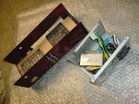
See this post for examples. Comment about case size applies here too, but yours is just that little bit larger and more accessible, so you should be ok I think.
Thanks for that info. The enclosure is 222 x 146 x 55 for the record.
Looking at the pics it seems you've used 4-pin plugs. I planned on using 3 pin plugs but these don't allow for a mains earth wire to run between both enclosures. I'm now thinking I should switch to a 4 pin setup?
EDIT:
I suppose I could run an earth strap external to the umbilical if it's possible (wise?) to sit both enclosures on top of each other?
Thanks
Last edited:
No, I use three pin XLR connectors for the power. The amplifier chassis does not need to be earthed, only the power supply.
My boards arrived today. Very impressed at the quality !!
Briefly contemplated finding a picture frame and hanging them on the wall until the rest of the components arrive.. 🙂
Then the next parcel opened had some of them so just waiting for the OPA27s which should be here tomorrow if the tracking proves accurate.
Briefly contemplated finding a picture frame and hanging them on the wall until the rest of the components arrive.. 🙂
Then the next parcel opened had some of them so just waiting for the OPA27s which should be here tomorrow if the tracking proves accurate.
I note the BOM states capacitors C10-13 are not needed if using OPA27 yet all the builds here and the build on the project page have them installed.
Are they recommended even with OPA27 ? (Mouser did not have them anyway so I didn't order them but thought to check here in case something had changed ?)
Are they recommended even with OPA27 ? (Mouser did not have them anyway so I didn't order them but thought to check here in case something had changed ?)
I note the BOM states capacitors C10-13 are not needed if using OPA27 yet all the builds here and the build on the project page have them installed.
Are they recommended even with OPA27 ? (Mouser did not have them anyway so I didn't order them but thought to check here in case something had changed ?)
The build instructions I received states;
C10-13 are optional 0.1uF ceramic bypass capacitors and are not required with low bandwidth op amps like the NE5534A etc
Don't know if OPA27 are considered low bandwidth...
HTH
Don't know if OPA27 are considered low bandwidth...
HTH
Neither do I...
I looked at their Data sheets and NE5534A listed at 10MHz and OPA27gp at 8MHz so presume the OPA27gp is "low bandwidth"
Assuming I'm not comparing apples with oranges in trying to interpret the datasheets...🙂
Perhaps I'll just get the caps and bung 'em in so any change I may make to opamps later won't require dismantling to solder them on..
I always put them in my builds.
Some people are allergic to ceramic caps, however, which is why I say they are optional in the Emerald with the usual op amps. If you are using OPA37 for example, they would be needed.
low bandwidth = GBWP 10 Mhz or less.
Some people are allergic to ceramic caps, however, which is why I say they are optional in the Emerald with the usual op amps. If you are using OPA37 for example, they would be needed.
low bandwidth = GBWP 10 Mhz or less.
I have no allergy's...🙂
Having done some more reading I see you favour a FET opamp for MM....
Is this for the first or both ?
Could I swap out one (first) OPA27 for a more suitable FET (any recommendations ?) and leave the second OPA27...?
Having done some more reading I see you favour a FET opamp for MM....
Is this for the first or both ?
Could I swap out one (first) OPA27 for a more suitable FET (any recommendations ?) and leave the second OPA27...?
Op amps can be mixed and matched freely. FET types might be fractionally quieter for the input stage with MM carts, BJT are preferred as the input stage for MC. For the second stage, you want good low distortion audio opamp.
Careful that if you use a FET input as IC1, the Emerald will probably not work with the gain switched to high (MC) because the input offset voltages is too large. It's fine in the MM position however.
Careful that if you use a FET input as IC1, the Emerald will probably not work with the gain switched to high (MC) because the input offset voltages is too large. It's fine in the MM position however.
My reclaimed transformer has 2x11v or 2x13v outputs...
Am I better to...
a)overvolt a little and use the 13v...?
b)overvolt a little and use the 13v and add heatsinks to the s-reg transistors?
c)undervolt a little and use the 11v..?
d) use the 13v and inline diodes to drop .7v ? (as measured that would give 13.1-.7=12.4)
e) use 13v and that's within 10% spec so live a little ...😉 ? 13.1 x 1.414=18.5 so that seems ok as 18v is recommended
Last edited:
I'd go with 13 V, no need for heatsinks. I'd only go with 11 V if it's a poorly regulated transformer and the low current voltage is over-spec.
(you want about 17-18 V CV into the V++. As low as 14 V will work, but 15 V is better to be safe. Don't go over 22 V or the caps 25 V limit comes into play.)
Thanks Richard.....transformer seems well regulated with no-load volts at 13.1v a side. So I will try with 18.5v rectified.
I note in another forum an emerald builder has this to say for a first test...
seems a good check that all is well before installing the opamps...
Any comments on this ?
I note in another forum an emerald builder has this to say for a first test...
Before you fit the opamps, power up the boards, check that the regulator is functioning correctly and adjust the midpoint using the trimpot so that the voltage is symmetrical – then fit the opamps
seems a good check that all is well before installing the opamps...
Any comments on this ?
It's always good practice to power up without the ICs in place, though it's not required to trim before the op amps are installed.
- Home
- Source & Line
- Analogue Source
- RJM Audio Emerald Phono Stage Help Desk