Pass DIY Addict
Joined 2000
Paid Member
I have a silly question and I think I'm missing something obvious, but can't figure out what it is. I was playing around with the PCB mounting technique for my Korg (x-mas version) and found an interesting behavior:
With the PCB screwed tightly to metal standoffs that are mounted to the chassis, everything works/sounds great! Then I lifted the PCB and isolated it from the metal standoffs with neoprene washers on top and bottom of the pcb to provide some vibration isolation. This made one channel buzz (wide spectrum white noise). The buzz is hard to hear with the input pot minimized and increases as the 51k volume control approaches max. Upon power up, the buzzing channel lights up more slowly than the quiet channel and at power down, the buzzing channel stays lit longer than the other one. Removing the washers makes everything behave well again.
So this is clearly a grounding issue: the obvious difference is that the chassis is not grounded when I use the neoprene washers, but given that the PCB mounting holes run the perimeter of the board and connect to the RCA jacks either way, what is the difference? Why the visible difference with the NuTube glow?
You're torquing the board differently and opening up less pristine solder joints?
I managed to catch up with my solder crimes, but one of the symptoms on the 10K variable pots was dimming of the channel on the NuTube. Touched up solder and it was fine.
I managed to catch up with my solder crimes, but one of the symptoms on the 10K variable pots was dimming of the channel on the NuTube. Touched up solder and it was fine.
So this is clearly a grounding issue: the obvious difference is that the chassis is not grounded when I use the neoprene washers, but given that the PCB mounting holes run the perimeter of the board and connect to the RCA jacks either way, what is the difference? Why the visible difference with the NuTube glow?
Check your power supply jack and wiring. Metal bushing types often have 3 terminals. Typically, a center pin plus, an isolated finger that connects directly to the plug barrel minus and a third that becomes disconnected from the finger terminal when the plug is inserted. However, the power supply barrel still touches the jack bushing, making connection to the bushing only.
If your PCB supply minus is connected to the switched terminal instead of the finger, then the chassis becomes the only way the power supply minus connects to the circuit.
Pass DIY Addict
Joined 2000
Paid Member
Remember that the plate of the tube is a high impedance spot, and is happy to
pick up on unshielded noise. If the chassis is not grounded, it becomes part
of the problem.
pick up on unshielded noise. If the chassis is not grounded, it becomes part
of the problem.
Pass DIY Addict
Joined 2000
Paid Member
Ah - I was considering the chassis to be "a shield" (not grounded) rather than "a shield with a drain" (grounded). I'll retry the washers and add a ground wire.
To really get rid of the specific frequency that starts the ringing you would have to isolate the solder connections that make it rigid.
Either the whole board isolated ( difficult ) or korg triode panel mounted with flexible wiring
And foam captured body surrounding the piece.
Regards
David
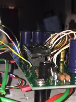
Yep, that works, (xmax board) just a quick lash up to see and yes 80% better than before when the tube was soldered directly to the board. Only rings with a firm tap on the case with a s/driver. Flexi leads and a nice foam cushion.
Ta
🙂
Attachments

Yes. The value depends on the Idss of Q1 and Q2. Ideally we want the current
through Q1 to be about 10% or so less than its Idss in the range from about 6 to
9 mA. The Idss of Q2 and R1 are used to set the current of Q2 to that figure.
Are those Q1 & Q2 idss should be :
2x matched
4x matched
or 8x matched ??
And is it ok to use matched K117?
Thanks.
Last edited:
Q1 should be from about 6 to 9 mA. Q2 and its Source resistor should
provide for current about 10% less than the Idss of Q1.
In the kits, the Q1's are matched, and the Q2's are also matched and
the appropriate resistor values are included to make these conditions.
provide for current about 10% less than the Idss of Q1.
In the kits, the Q1's are matched, and the Q2's are also matched and
the appropriate resistor values are included to make these conditions.
Enochrome: I would recommend a few things:
1) Double check ALL parts - make sure correct value parts are in the correct locations.
2) Since you said you had trouble soldering, it might be worth reflowing each of your solder joints. Let your iron warm up, touch each solder joint again to remelt it, then let it cool.
3) When you have reflowed all of the solder joints, check each one with a magnifier under a bright light. Make sure you don't have any inadvertant solder bridges where they shouldn't be. When solder pads are close together, take a fine blade screwdriver and scratch between the pads to make sure there is no solder where it shouldn't be.
4) If things don't improve after this, follow 6L6's advice: post well-lit, in-focus, decent-resolution images so we can see what is going on.
Did you power the board up with the capacitors the wrong way round? If so they may need to be replaced.
You definitely need to go over your soldering. The solder should ideally flow from the bottom surface to the top - for example the diode D1 has big air gaps.
Do you have any pics of the bottom side?
Do you have a multimeter?
Sorry for the late reply! Life and the such got in the way. I will take both of your advice and look into going through all those areas. I did glance at the board after your reading your posts and did notice some areas of concern. I also might purchase Nelson's board and start over with the Nutube, I heard his a board does not have the issue with an oscillation that the Millet board has. Thanks again and I will let you know how it turns out. Much appreciated.
For the ones who uses Salas Ultrabib SSLV1.3, which type of board do I need? Positive or negative?
For the ones who uses Salas Ultrabib SSLV1.3, which type of board do I need? Positive or negative?
Positive. I used a 4 ohm resistor for R1 others have used 3R3.
I think it will not do much difference considering the Coloration and distortion from the Nutube.
The Xmas board (generously gifted by Papa) came with the Toshibas. For a friend, I am about to build a DIY store board with the Fairchilds. I will do an A-B listening test after completion and post my results.Hi,
Dies anyone tried the nutube with toshiba 2sk170?
Regards
- Home
- Amplifiers
- Pass Labs
- B1 with Korg Triode