Better SQNot a critical question, just out of interest, What made you decide on C-core?
Thanks
Thanks for your input.
Usually 6C33 builders use primary 600Ω, but 500 and 1000Ω also was used some years ago.
I have see on web a brown paper used as insulation, but tape or some kind of cloth also could be used.
Ordinary paper will oxidize/degrade/crumble over time, special electrical grades are available, or synthetic replacements like nomex paper (which I've used when rewiring a motor - its extremely tough mechanically as well as temperature resistant and insulating - recommended).
Thanks for inform, Nomex also used in speakers VC.Ordinary paper will oxidize/degrade/crumble over time, special electrical grades are available, or synthetic replacements like nomex paper (which I've used when rewiring a motor - its extremely tough mechanically as well as temperature resistant and insulating - recommended).
Better SQ
C-Cores come with very thin laminations which lower eddy current losses. Nice. On the other hand I am not sure what core materials are offered as c-cores. I am aware of nanochrystalline, amorphous and grain oriented steel. Does anyone offer nickel c-cores?
For better "SQ" M-Cut is a good option as it keeps the airgap within the winding.
Nanochrystalline and amorphous are expensive, to me 0.1mm HiB or GOSS are suffice.C-Cores come with very thin laminations which lower eddy current losses. Nice. On the other hand I am not sure what core materials are offered as c-cores. I am aware of nanochrystalline, amorphous and grain oriented steel. Does anyone offer nickel c-cores?
For better "SQ" M-Cut is a good option as it keeps the airgap within the winding.
What exactly is ''M-cut''?
Morgan´s is excellent but "modern":The Valve Amplifiers/Morgan Jones have only 10 pages on OPTs.
This book have the full recipe?
I was talking tube books from early 40´s to early 60´s tops.
One example being books from tube factories, think Philips, Mullard, Siemens,etc. who suggested schematics and included transformer blueprints , obviously because they wanted to make it easy using their own "glass" products.
Also British Hi Fi books from 50´s and early 60´s.
Looks intersting, if you could email me these in PDF would be great.Morgan´s is excellent but "modern":
I was talking tube books from early 40´s to early 60´s tops.
One example being books from tube factories, think Philips, Mullard, Siemens,etc. who suggested schematics and included transformer blueprints , obviously because they wanted to make it easy using their own "glass" products.
Also British Hi Fi books from 50´s and early 60´s.
FullRangeMan,
I detect that much of the thinking here is power transformer orientated. Wire gauge, insulation etc. would mostly follow the design of an OPT, not initiate it.
Output transformer design would require the following:
1. Power to be handled
2. Impedances required
3. Primary inductance required
4. Leakage inductance P:S
5. Frequency range to be acquired
(In this respect points 3 and 4 cannot be separately/independantly handled
from point 5.)
6. D.C. to be handled (as in the quiescent (standing) current drawn by the
power valve.)
7. Secondary sections to be configured such that full secondary is used for all
loudspeaker impedances which are catered for. (This by using
series/parallel connections of all sections. Simple taps on secondaries
would leave some windings floating, giving different leakage impedances for
different output configurations.)
Some of these characteristics cannot easily achieved by calculation alone.
The influence (mostly on NFB) of whatever final characteristics result, can
however be easily compensated for afterwards in the electronic circuitry. (This practice of trimming afterwards in a completed unit, is universally used because of relative ease. The selected component values are then adopted in the final design.)
A screen between P/S is not normally used. It serves no purpose there, whilst possibly increasing inter winding capacitance. (In OPT design folks are often worried about the effect of leakage impedance on h.f. response, neglecting that of inter-winding capacitance. The latter can have the major effect in h.f. where 4 or more secondary sections are used, depending.
But this cannot become a tutorial. Members interested in complete design are referred to the excellent design procedure found in 'Radio Designer's Handbook' edited by F. Langford-Smith, chapter 5 sect. 3 supra (out of print for several decades now, but available on the internet.) Other publications exist of which I have no knowledge.
Last edited:
Here's another list of papers and articles. American Radio History and History of Recording have some of the magazine issues mentioned in the list and a few of them are linked at Chris Preston's nice page HERE. Detailed searches with title and author can net some of the others.

Hi FRM,
I try to help you.
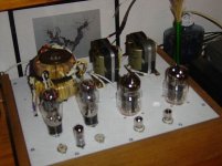
Two decades ago I DIY-ed D3a-6C33C SET (one cathode heating). I'm sending a bad picture of it, sorry for bad quality - painted with the first generation of mobile phones.
OPT is my own hand-wound. I finished winding for about 2 months 🙂).
For OPT calculate I used this:
Transformers
For the core I used SM102b double C core from Vacumschmeltze; 0.1 mm lamm. grain oriented steel.
I had a total of 9 sections: 5 sections of the primary winding and a total of 4 secundary. With different conections of secundary you can get 1, 4, 8 and 12 ohms.
For insulation between layers I used thin teflon (rewinded 4-5 pieces of Russian teflon capacitors). For insulation between prim and sec I used additional insulation (modern paper/mylar insulation 0.1mm).
From my memory: primary was with 0.2 mm wire (good for manual winding) and for secundary I used 0.8 mm wire.
And yes..
The final gap came down after experimental listening. It was 0.2 mm if I remember well.
I hope I helped you a little.
Best diying.
I try to help you.
Two decades ago I DIY-ed D3a-6C33C SET (one cathode heating). I'm sending a bad picture of it, sorry for bad quality - painted with the first generation of mobile phones.
OPT is my own hand-wound. I finished winding for about 2 months 🙂).
For OPT calculate I used this:
Transformers
For the core I used SM102b double C core from Vacumschmeltze; 0.1 mm lamm. grain oriented steel.
I had a total of 9 sections: 5 sections of the primary winding and a total of 4 secundary. With different conections of secundary you can get 1, 4, 8 and 12 ohms.
For insulation between layers I used thin teflon (rewinded 4-5 pieces of Russian teflon capacitors). For insulation between prim and sec I used additional insulation (modern paper/mylar insulation 0.1mm).
From my memory: primary was with 0.2 mm wire (good for manual winding) and for secundary I used 0.8 mm wire.
And yes..
The final gap came down after experimental listening. It was 0.2 mm if I remember well.
I hope I helped you a little.
Best diying.
Attachments
Last edited:
Thanks RajkoM you most kind,Hi FRM,
I try to help you.
Two decades ago I DIY-ed D3a-6C33C SET (one cathode heating). I'm sending a bad picture of it, sorry for bad quality - painted with the first generation of mobile phones.
Best diying.
I appreciated your detailed info.
That is a really beautiful amp.
Dear Johan I thankyou for your tech post.FullRangeMan,
I detect that much of the thinking here is power transformer orientated. Wire gauge, insulation etc. would mostly follow the design of an OPT, not initiate it.
Iam not near your level so I have something to think
What exactly is ''M-cut''?
Attachments
Not sure how much you want to get into reading but you might also net stuff of interest searching posts by some of the winders here, Cerrem, Yvesm, Pieter T etc.
Cerrem's comments on the differences between C-core and EI core transformers are very interesting and not things that you find easily from general reading.
Cerrem's comments on the differences between C-core and EI core transformers are very interesting and not things that you find easily from general reading.
Thanks for the heads-up it will be useful.Not sure how much you want to get into reading but you might also net stuff of interest searching posts by some of the winders here, Cerrem, Yvesm, Pieter T etc.
Cerrem's comments on the differences between C-core and EI core transformers are very interesting and not things that you find easily from general reading.
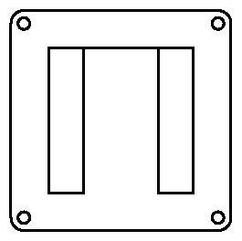
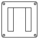
This image seems similar to an assembled EI core.
Ah, ok. The crucial difference is that the lamination is one single piece. The airgap is not across the whole core but only in the center piece. That type of core can't be mashine assembled but has lower eddy current losses. I get mine from a distrubutor of Vacuumschmelze.
- Home
- Amplifiers
- Tubes / Valves
- What to Ask When Ordering an Output Transformer?