I invested in Earthworks M30 mic and Roland Quad Capture USB soundcard. No regrets, nor doubt about precision.
I sent the mic once for recalibration measurements, and it was within +-0.3 dB up to 24kHz so I don't use any correction. Pressure distortion tolerance according to specs is also very good. I've got very clear and repeatable THD measurement results in ARTA measuring different drivers, even at unbearably loud volumes.
The only confusing thing with this mic was that calibration data in file provided by manufacturer started from 600Hz with 0.5dB abrupt "jump" from 0dB. I believe they have fixed this by now.
The M30 is certainly a good buy, but an expensive purchase for many hobbyists, and there are interesting loudspeaker drivers to buy for the money. I think you can come close (up to 20khz) with much less money, buy 10-20 panasonic capsules, measure them and arrange them through performance, remove those that stand out too much and use only those that are similar. I'm sure you will end up with a handfull of microphones that are super-correct at a very small cost 🙂
I invested in Earthworks M30 mic ... The only confusing thing with this mic was that calibration data in file provided by manufacturer started from 600Hz with 0.5dB abrupt "jump" from 0dB. I believe they have fixed this by now.
I saw the same with mine, so I asked EarthWorks about it. The cal file you get is relative to their (compensated) measurement microphone. Just make sure the level at 1 kHz corresponds to the sensitivity they quoted on the spec sheet. You may have to shift the values in the compensation file by some constant offset to make it fit.
Following up on my recent posts regarding the Behringer UMC202. I exchanged the unit for the PreSonus 26C. All loopback measurements result in less than .002% THD. Very happy with the unit.
One thing that I learned through all this... unlike my old M-Audio FW410, to use the mic preamp input an XLR connector must be used. I looked at several different brands of these devices and they all seem to be this way.
One thing that I learned through all this... unlike my old M-Audio FW410, to use the mic preamp input an XLR connector must be used. I looked at several different brands of these devices and they all seem to be this way.
..I exchanged the unit for the PreSonus 26C. All loopback measurements result in less than .002% THD. Very happy with the unit.


-if you want to do a wide range of electrical measurements the next purchase would probably be this:
The L|A Autoranger | Linear Audio NL
Last edited:
I invested in Earthworks M30 mic..
The M30 is certainly a good buy, but an expensive purchase for many hobbyists, and there are interesting loudspeaker drivers to buy for the money.
I think you can come close (up to 20khz) with much less money..
..at less than half the price:
EMX-7150 Measurement microphone (bulk) - iSEMcon_US
-and you could probably get an even better calibration file for it (..maybe from Cross-Spectrum).
Speaking of Cross-Spectrum, they carry MicW ..if you really wanted to spend as *much as the Earthworks mic., you could ask Cross-Spectrum about getting a M215 from them with their additional higher quality calibration.
Cross·Spectrum - Calibrated MicW i436 Microphones for Sale
MicW
*actually it should still be less.
Last edited:
How to check Babyface line loopback in ARTA? Not sure if I'm in CC mode. Connected R in/out but level is low. Left level is higher but low too.
Found it was driver related now I see TotalMix. Loopback ok?
Attachments
Last edited:
Thanks all!
Operator error it was 🙂 Cut the link between channel grounds (pin3 <> pin3) and it seems legit now. Next up TS parameters and semi-inductance for weekend fun 😎
Can you do schematic with mic added and switch (imp/spl)?
P48 has no influence on imp? Babyface has line and mic same cable.
Hi, Phantom power is the reason I didn't do the measurement box 🙂
It takes a bit longer to swap cables than flick a switch but not too bad unless you measure for living. Fidling with the cable spaghetti gives some time to think and check twice if the phantom is on or off.
It takes a bit longer to swap cables than flick a switch but not too bad unless you measure for living. Fidling with the cable spaghetti gives some time to think and check twice if the phantom is on or off.
The older babyface manual says
"
48V Phantom power on/off
Use Select key and select “In”
Push the Encoder to select the desired channel (left, right, both)
Push and hold the encoder until the orange 48V LED(s) turn on/off.
"
It might be the same with the newer babyface pro as well
"
48V Phantom power on/off
Use Select key and select “In”
Push the Encoder to select the desired channel (left, right, both)
Push and hold the encoder until the orange 48V LED(s) turn on/off.
"
It might be the same with the newer babyface pro as well
ARTA 1.9.2
ARTA 1.9.2 is available since wednesday: ARTA Download
Also some updated papers: http://www.artalabs.hr/AppNotes/AP1_MeasuringBox-ver-2-Rev1Eng.pdf
Regards
Heinrich
ARTA 1.9.2 is available since wednesday: ARTA Download
Also some updated papers: http://www.artalabs.hr/AppNotes/AP1_MeasuringBox-ver-2-Rev1Eng.pdf
Regards
Heinrich
ARTA 1.9.2 is available since wednesday: ARTA Download
Also some updated papers: http://www.artalabs.hr/AppNotes/AP1_MeasuringBox-ver-2-Rev1Eng.pdf
Regards
Heinrich
Thank you very much Mrs. Some english translation Limp tutorial 2.5 ?
Some question, 0.1 or 0.2 volts is the terminal voltage?
Thank you.
Hi Rich08,
yes it's the terminal voltage (original manual, fig 3.1 or 3.2, left in).
The following pic shows max THD (as defined in original Manual on page 25 "a) Procedure in Stepped sine mode") as function of terminal voltage for 3 different drivers.
Regards
Heinrich
yes it's the terminal voltage (original manual, fig 3.1 or 3.2, left in).
The following pic shows max THD (as defined in original Manual on page 25 "a) Procedure in Stepped sine mode") as function of terminal voltage for 3 different drivers.
Regards
Heinrich
Attachments
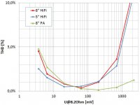
The following pic shows max THD ... as function of terminal voltage for 3 different drivers.
Are you sure this is THD? The high values at low drive voltages make me think this might be THD+N. Or is this maybe some mechanical stiction in the drivers that cause higher distortion ratios at low drive voltage?
Are you sure this is THD? The high values at low drive voltages make me think this might be THD+N. Or is this maybe some mechanical stiction in the drivers that cause higher distortion ratios at low drive voltage?
The measurement shows THD, but when signal is low the noise contributes to THD value. Some other effects probably arises like hysteresis of suspension and...
Heinrich has made nice measurements to show that we can find the excitation level that will gives as "small signal regime", which is optimal for measurement of impedance and TSP estimation.
Small signal regime is important because in estimation of TSP we are using assumption of constant BL or constant compliance.
How to find optimal value of voltage is a problem as voltage is not the same on resonance and in pass-band (except when referent resistor is much smaller than Re)
We must use two step process with stepped sine excitation. In first measurement we find frequency with maximum THD and than try with larger or smaller voltage to get minimum THD.
What frequency region is important? Generally it is on frequencies at or bellow resonance, as in that range membrane has large displacement and compliance additionally exhibits creep effect (change of compliance with frequency).
Ivo
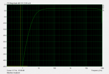
I'm sorry for noob question but I still not able to understand clearly how to set proeprly Gating window in ARTA in measured impulse reponse.
I try to measure 10" speaker with install height 950mm and on same height mic with a distance between them 1m. Vituixcad says that splitting frequency to connect with nearfiled measurement is about 3xx Hz and windows time until first reflection is ~3.3ms
But on every video\articles I see only one impulse while I see two of them. How so set start\stop gating window properly?
I use dual channel mode measurements. Pic of measurements is below
Hi Rich08,
yes it's the terminal voltage (original manual, fig 3.1 or 3.2, left in).
The following pic shows max THD (as defined in original Manual on page 25 "a) Procedure in Stepped sine mode") as function of terminal voltage for 3 different drivers.
Regards
Heinrich
Thank you for answer. With resistor value of nominal loudspeaker impedance?