
Sometimes you need more copper! Or better copper?
Or better shielding? I don't know.
But what I can say for sure: Thanks for this toy, Mr. Pass!
It sounds wonderful.

Greets
Dirk
Or better shielding? I don't know.
But what I can say for sure: Thanks for this toy, Mr. Pass!
It sounds wonderful.
Greets
Dirk
Nice build!
Are the "Adjust 2nd/3rd" pots connected?
Something you want to adjust "on the fly"?
Has Korg Pre voltage swing enough to drive BA-3?
Are the "Adjust 2nd/3rd" pots connected?
Something you want to adjust "on the fly"?
Has Korg Pre voltage swing enough to drive BA-3?
Sometimes you need more copper! Or better copper?
Or better shielding? I don't know.
Hallo Dirk,
I had the best experiences with less copper ... 😀
I used to use shielded microphone cable, that worked quite well, but more recently, for all input wiring, I am using wire wrap wire - silvered OFC copper, AWG30, such as that one here:
Kynar Wire Lotdraht Montageleitung Lotkabel Led Modding AWG 30 / OFC versilbert | eBay
Works very well, tightly twisted ... hum pick-up, if there is some, can usually be minimized by thoughtful routing ... 😉
I discovered this actually following a hint by Zen Mod some time ago ... 😎
Viele Grüße,
Claas
B1/Korg PCBs + JFETs are now back in stock. We're also gathering interest in a full kit, which is currently at the prototype stage, and you can register interest on this page.
answer to MEPER #1966
Hello Meper,
nice to hear from you again!
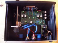
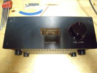
The adjustment pots are connected. I did not use the pots on the pcb. I wired it
to the backplate pots to adjust also if the case is closed. The wires are underside of the pcb.
I used BOURNS 10kohm precision trimpots (10 turns). Makes exact adjustments easy. But I forgot to make a connection from T7/T8 to the outside of the case.
So, to measure I have to open the case again. Or I have to count the amount of
turns (sure not that exact).
In my combination at the moment with the BA-3 poweramp - the B1 Nutube drives the BA-3 with ease.
But I use a easy to drive loudspeaker (4 Ohm, 91dB/W/m, 2-way d'appolito) and
my BA-3 is running close to the edge (+/-34.9V rail voltage, BA-3 gain stage and BA-3 complementary output board). In the gain stage I use original TOSHIBA JFETs from punkydawgs. They run hot!).
Greets
Dirk
Hello Meper,
nice to hear from you again!
The adjustment pots are connected. I did not use the pots on the pcb. I wired it
to the backplate pots to adjust also if the case is closed. The wires are underside of the pcb.
I used BOURNS 10kohm precision trimpots (10 turns). Makes exact adjustments easy. But I forgot to make a connection from T7/T8 to the outside of the case.
So, to measure I have to open the case again. Or I have to count the amount of
turns (sure not that exact).
In my combination at the moment with the BA-3 poweramp - the B1 Nutube drives the BA-3 with ease.
But I use a easy to drive loudspeaker (4 Ohm, 91dB/W/m, 2-way d'appolito) and
my BA-3 is running close to the edge (+/-34.9V rail voltage, BA-3 gain stage and BA-3 complementary output board). In the gain stage I use original TOSHIBA JFETs from punkydawgs. They run hot!).
Greets
Dirk
Attachments

answer to jwjarch #1967
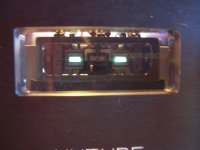
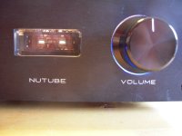
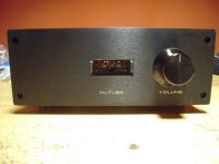
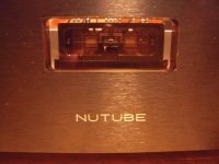
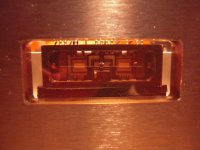
Some pics from the 'glowing' or 'burning' front.
(I have posted a few pics from the front before in this thread - but no problem)
Greets
Dirk
Some pics from the 'glowing' or 'burning' front.
(I have posted a few pics from the front before in this thread - but no problem)
Greets
Dirk
Attachments
B1 NUTUBE experience
Also important - absolutely no hum or noise from this little babe.
Greets
Dirk
Also important - absolutely no hum or noise from this little babe.
Greets
Dirk
Do you invert the speaker terminals so you end up with negative phase 2nd harmonic?
If you adjust pots according to NP as a starting point?
If you adjust pots according to NP as a starting point?
to MEPER #1944
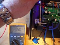
Hello MEPER,
speakers are connected inverted.
Setting T7/T8 at around 9.5V is the recomendation from Nelson Pass article as a starting point:
After a few minutes and no smoke, we adjust the T7 and T8 voltages as follows:Voltage at 12 VDC is approximately the 2nd harmonic null point where we get about .3 %distortion in 3rd harmonics. As we go lower we start getting positive phase 2nd harmonic, and itwill hit 1.5% at 1 volt AC output with about 9.5 VDC on the T7 or T8 test points. Voltages higher will give negative phase second harmonic.This is a reasonable calibration - 0.1V either way changes the distortion by about 0.1%Clockwise on the pot from the null spot makes for less Plate voltage, and positive phase second harmonic, counterclockwise makes for more negative phase second harmonic.If you have a distortion analyzer which gives you the percentage but not the phase, then just start out with the Plate voltage high (CCW pot) and turn it clockwise to the point where it is minimum, and then go further for + phase, or back up for - phase.The reference setting for this project, are 9.5V on T7 and T8, which gives a positive phase at about 1.5% at 1 volt output. You are free to set it elsewhere.
Greets
Dirk
B1/Korg PCBs + JFETs are now back in stock. We're also gathering interest in a full kit, which is currently at the prototype stage, and you can register interest on this page.
Thanks for the notice! I regretted not ordering it the first time it was in the store, so I'll definitely be ordering it this time 🙂
to all B1 NUTUBE builders
Hello members,
if you missed to read Nelson Pass article about the B1 KORG NUTUBE:
Go to the diyAudiostore - KITS - B1 Buffer w/Korg Triode Pre-Amplifier-
click on the left pic - scroll down to 'The DIY Nutube Preamp (PDF)'.
Very good article with very important information - all the values at Testpoints
on the pcb..... positive/negative 2nd harmonic...
Greets
Dirk
to dtaylo3
Thanks for the kind words!
This is all a result of my disease - audiophility
Incurable? 😀
Greets
Dirk
Thanks for the kind words!
This is all a result of my disease - audiophility
Incurable? 😀
Greets
Dirk
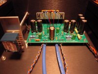
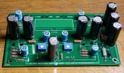
This is so far my Korg build came this afternoon. Still missing an important component.
Instead of the 2x10R in the RCRC filter I have installed 2.2 mH ferrite chokes that can handle 150 mA or so and has DC resistance of 8 - 8.5 ohm. Will see how that goes. I will use Meanwell 24V supply so good to have some HF rejection. It is just an "experiment".
For the 10uF caps I used what I had and used what measured best using a LCR bridge. They are Nichicon but not from the "audio" category. The FG's (Fine Gold) measured not that good. The green bipolar Nichicon measured decent but not as good as the ones I used (especially not at high frequencies).
Attachments
Meper
Be sure to post your finds on the Meanwell switcher, I have an extra and was thinking of using it for this build also but wasn't sure it would be clean enough.
Be sure to post your finds on the Meanwell switcher, I have an extra and was thinking of using it for this build also but wasn't sure it would be clean enough.
- Home
- Amplifiers
- Pass Labs
- B1 with Korg Triode