Hi JSA,
You need to wire the pot as a voltage divider. I can never remember the CCW/CW
nomenclature (and also I think I wired my pot upside down), but this
is roughly what I did: If you look at the three pins of the pot for each channel
then input from RCA goes to say pin 1, input ground goes to pin 3, then wire from
pin 3 goes to ground on PCB and wire from pin 2 goes to input of PCB. You may
have to switch pin 1 & 3 depending on how you're viewing the pot.
Hope that doesn't cause more confusion. 🙂
Dennis
Hi Dennis, thanks for your reply. If I’ve understood you correctly, hopefully 🙂 , then I should wire the pots for each channel like this?
Attachments
Yes, that's what I meant. 🙂
You may have to switch 1 and 3 around depending on the orientation of
the pot. You just want it so that when your pot is cranked to the max
volume position that the measured resistance between your signal pin 2 and the
chosen ground pin is at max level. (i.e. the resistance value your pot)
Dennis
You may have to switch 1 and 3 around depending on the orientation of
the pot. You just want it so that when your pot is cranked to the max
volume position that the measured resistance between your signal pin 2 and the
chosen ground pin is at max level. (i.e. the resistance value your pot)
Dennis
Yes, that's what I meant. 🙂
You may have to switch 1 and 3 around depending on the orientation of
the pot. You just want it so that when your pot is cranked to the max
volume position that the measured resistance between your signal pin 2 and the
chosen ground pin is at max level. (i.e. the resistance value your pot)
Dennis
Thanks for the help Dennis, greatly appreciated!
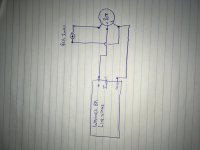
pot with shaft to you , pins down
pins from left are
- GND (to RCA and from pcb)
- signal hot to pcb (wiper)
-signal hot from RCA
pins from left are
- GND (to RCA and from pcb)
- signal hot to pcb (wiper)
-signal hot from RCA
Hi JSA,
You need to wire the pot as a voltage divider. I can never remember the CCW/CW
nomenclature (and also I think I wired my pot upside down), but this
is roughly what I did: If you look at the three pins of the pot for each channel
then input from RCA goes to say pin 1, input ground goes to pin 3, then wire from
pin 3 goes to ground on PCB and wire from pin 2 goes to input of PCB. You may
have to switch pin 1 & 3 depending on how you're viewing the pot.
Hope that doesn't cause more confusion. 🙂
Dennis
Mine is slightly more complicated by having a selector switch. In the beginning, I wired one input as you say, without selector. I think things got messed up when I "rewired" things.
Russellc
pot with shaft to you , pins down
pins from left are
- GND (to RCA and from pcb)
- signal hot to pcb (wiper)
-signal hot from RCA
Thanks for responding Zen Mod. So just reverse 1 & 3 in my wiring diagram and Suggestion from Dennis?
This is my BA-3 preamp wiring. I have used this wiring for BA-3 and other preamp that I built and it works just fine. Hope it helps! My wiring has the pot and selector
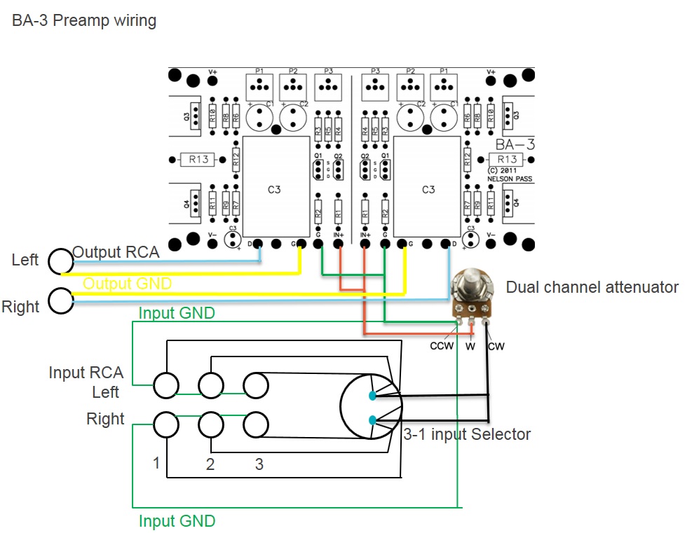
This is my BA-3 preamp wiring. I have used this wiring for BA-3 and other preamp that I built and it works just fine. Hope it helps! My wiring has the pot and selector
It does, assuming I got the right pic here, (post #159) these ladder type pots are slightly more confusing. Plus, I had a single input hooked up at first with selector by passed. Somewhere in the re wire I messed up. Or have a bad pot. I strongly suggest the former rather than the latter!
https://www.diyaudio.com/forums/pass-labs/258022-ba-3-preamp-build-guide-4.html#post4301088
Wired my BA3 like this: (post #163)
https://www.diyaudio.com/forums/pass-labs/258022-ba-3-preamp-build-guide-4.html#post4301194
Russellc
Last edited:
I have a hot air attachment for my Weller gas iron. Would it be possible to first apply a bit of solder on each pad for the smd components and the place the component on top of that and then use the hot air to melt it down?
That would be my first try when I get these boards.
MEPER, you could give that method a try although having a dedicated hot air gun you know exactly what temperature the air is at and how long. Maybe practice on some cheaper smd parts first to make sure your hot air attachment gets hot enough, but not so hot it burns the parts. That said, if I didn’t have the hot air gun I would just stick to the bamboo skewer and soldering iron method discussed earlier in the thread.
wdecho said:I have never used a hot air gun such as the Yaogong, how do you keep the air from moving the part around? Tell us more about technique using it.
wdecho, this is the technique I used on these boards and it worked very well.
1. Clean your board(s) first
2. Put a small amount of solder paste on each pad and set smd parts on board. The solder paste holds the parts in place surprisingly well. I haven’t had a part blow away yet, no mater how small
3. Using the medium size tip, set hot air to 200C and fan speed between 5-6
4. Heat both sides of the board back and forth for about 30 seconds
5. Turn the heat up to 400C and concentrate the air stream more around the solder paste pads. When the solder melts it goes shiny and pulls the part into place perfectly on the pads
MEPER,
wdecho, this is the technique I used on these boards and it worked very well.
1. Clean your board(s) first
2. Put a small amount of solder paste on each pad and set smd parts on board. The solder paste holds the parts in place surprisingly well. I haven’t had a part blow away yet, no mater how small
3. Using the medium size tip, set hot air to 200C and fan speed between 5-6
4. Heat both sides of the board back and forth for about 30 seconds
5. Turn the heat up to 400C and concentrate the air stream more around the solder paste pads. When the solder melts it goes shiny and pulls the part into place perfectly on the pads
Thanks for info, tip. Having never had or used a hot gun for smd parts it helps to have someone that has to tell their technique.
I carefully chased down my wiring, from inputs (3 of them) to selector, to volume pot to board for both channels with no luck. I did find one wire unsoldered on the selector switch but that wasn't it.
Maybe I just am looking over the mistake. I will take some close up photos and post them for scrutiny.
I have some simple Alps pots that are 100K I am thinking of installing in temporary basis, either as is, or use 2 of them with each pots strapped for as 50K mono pots if 100 is too high.
If pic pass scrutiny here, I will sub the pot to determine if I have a bad pot. Still think I have miss wired, but I sure can't see it!
Russellc
A few sets.
Thank you Jim. I received the boards in the mail!
Regards,
Tom
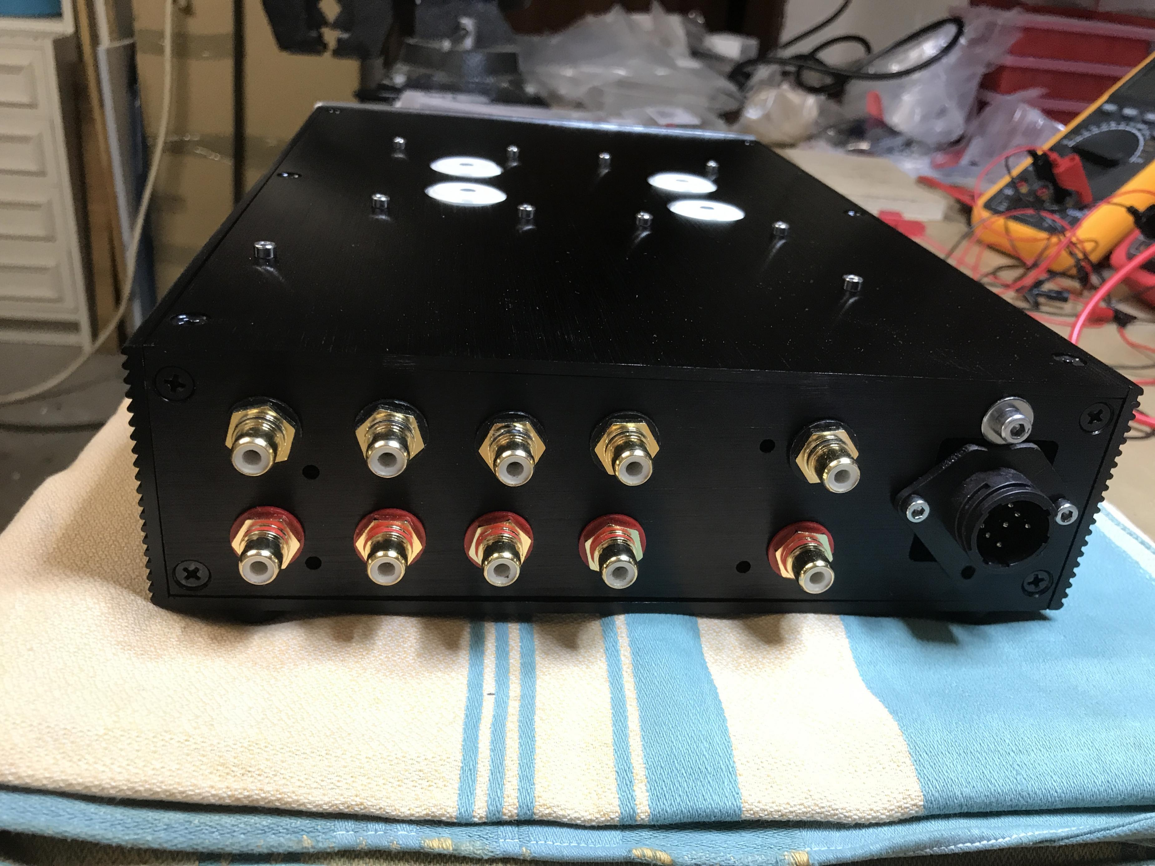
While I am waiting on my purple boards (Thanks Jim !), I am gathering information, build lists of parts and have already ordered a case with volume control and input switching.
6L6 encouraged me to share lots of info and pics of my build ... not much to show yet from the actual build, but I ordered this case:
HIFI Remote volume Controller preamp pre-amplifier audio 128 steps /4 way input | eBay
This is the exact same case I have used for my Aikido preamp a year ago. It is being sold as a passive preamp, having relay-based volume control and four inputs. This case hadn't been on the website anymore, but I contacted Min of the seller and he/she put it up for me again. Apparently customers were complaining of the high shipping cost, because for more than 2 kg of weight the seller was only able to use express shipping ... so on the website was now only a shorter (and therefore lighter) case (roughly 200 mm in depth), and that would not have had enough space to build an active stage into it.
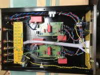
A few impressions on how I modified this case to put my Aikido into it:
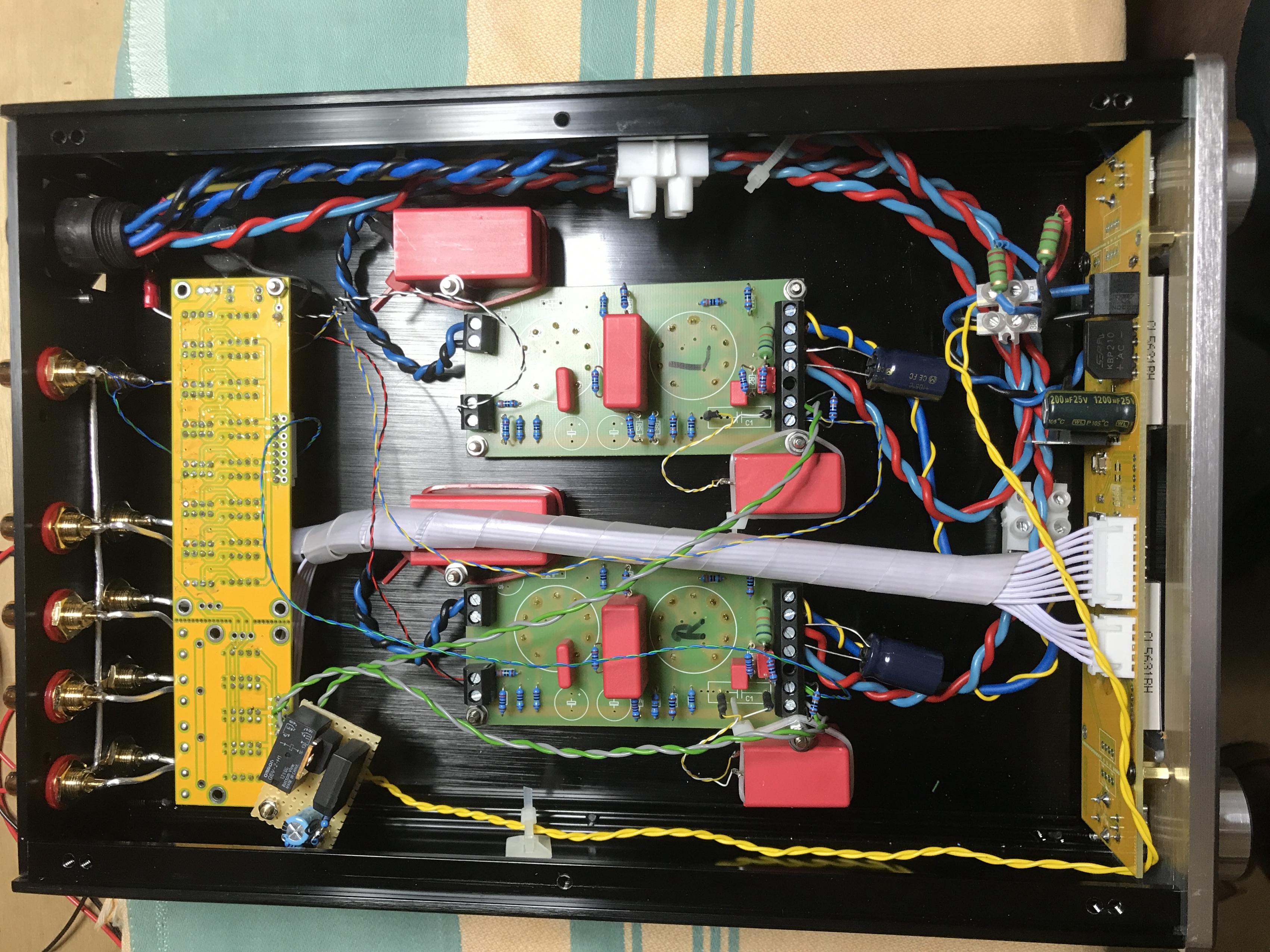
I hung everything from the ceiling, as I do in most of my tube-based builds.
Also, I built an external PSU from a number of parts I had leftover from a modding run of my DIY 2A3 SE amp, and some more I chanced upon on eBay.

Inside the case, there's the filament transformer, a big choke and three regulators, for all voltages used. So the chassis is quite full as well ...😀
Of course, the PSU could power a power amp also, and I might build an EL84 PP amp with it at one time ... 😛
For Wayne's linestage, I will probably build the PSU into a shallower version of the ModuShop Galaxy Maggiorato I used (230 x 280 mm, 2U).
I have also ordered two different linear bipolar adjustable PSU / regulator boards from eBay to try. They will take some time to get here, so more time for preparations ... 🙂
Best regards,
Claas
6L6 encouraged me to share lots of info and pics of my build ... not much to show yet from the actual build, but I ordered this case:
HIFI Remote volume Controller preamp pre-amplifier audio 128 steps /4 way input | eBay
This is the exact same case I have used for my Aikido preamp a year ago. It is being sold as a passive preamp, having relay-based volume control and four inputs. This case hadn't been on the website anymore, but I contacted Min of the seller and he/she put it up for me again. Apparently customers were complaining of the high shipping cost, because for more than 2 kg of weight the seller was only able to use express shipping ... so on the website was now only a shorter (and therefore lighter) case (roughly 200 mm in depth), and that would not have had enough space to build an active stage into it.
A few impressions on how I modified this case to put my Aikido into it:
I hung everything from the ceiling, as I do in most of my tube-based builds.
Also, I built an external PSU from a number of parts I had leftover from a modding run of my DIY 2A3 SE amp, and some more I chanced upon on eBay.
Inside the case, there's the filament transformer, a big choke and three regulators, for all voltages used. So the chassis is quite full as well ...😀
Of course, the PSU could power a power amp also, and I might build an EL84 PP amp with it at one time ... 😛
For Wayne's linestage, I will probably build the PSU into a shallower version of the ModuShop Galaxy Maggiorato I used (230 x 280 mm, 2U).
I have also ordered two different linear bipolar adjustable PSU / regulator boards from eBay to try. They will take some time to get here, so more time for preparations ... 🙂
Best regards,
Claas
Attachments


Last edited:
Thanks Jim! I found a set in the mailbox today 😀
Still waiting for mine 🙁
As did I, thanks for going to the trouble. Will solder up new boards tomorrow, with larger output devices.
As to my volume pot issues, I took one of my BA3 FE units out of service, removed the cover and compared wiring. There it is, wired inputs and outputs backwards!
All is working fine now. Whew!
Russellc
As to my volume pot issues, I took one of my BA3 FE units out of service, removed the cover and compared wiring. There it is, wired inputs and outputs backwards!
All is working fine now. Whew!
Russellc
- Home
- Amplifiers
- Pass Labs
- Wayne's BA 2018 linestage