Hello,
I wanted to convert my BA-3 which I operate as a preamp in the balance version.
- If I read the schematic correctly, I only have to change R 5.
The + - 24 volt input voltage remain the same as the normal Ba-3, is that correct.
I wanted to build the BA1 as balance version with 4 output stages per channel as amplifier.
Is enough for a transformer of 600VA / 2X18V, for 4 (balance 8) output stages per channel.
Hallo,
ich wollte meine BA-3 die ich als Vorverstärker betreibe in die balance version umbauen.
- Wenn ich den Schaltplan richtig gelesen habe muss ich nur R 5 ändern.
Die +- 24 Volt Eingagsspannung bleiben auch wie bei der normalen Ba-3, ist das richtig.
Ich wollte die BA1als balance Version mit 4 Ausgangsstufen je Kanal als Verstärker bauen.
Reicht ein Trafo von 600VA / 2X18V, für 4 ( balance 8 ) Ausgangsstufen je Kanal.
Decided to have a go at doing my own BBA3FE a few weeks ago and it seems to be working. Need to do some final calibration to ensure that the bias is stable, but so far so good 😀
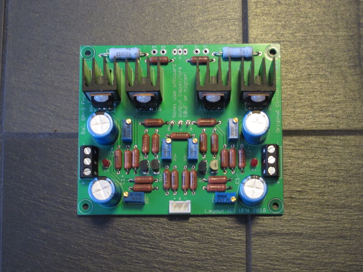
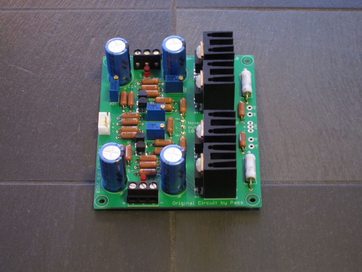
Offboard DC-blocking caps not shown 😉
Offboard DC-blocking caps not shown 😉
hi, I was completing the assembly of the components on the pcb of the Burning Amp BA-3 as a guide 6L6, now, I saw this thread on the balanced version, coreggetemi if I'm wrong, in case I wanted to build the version b changes to remove the resistors R5 from 100 Ohm on both channels of the BA-3 board and join them with a 200 ohm resistor? connect the positive input to a channel, the negative to the other channel, mass in common? and at the output of the 2 pcb of power one the positive speaker and the other the negative speakers? quite right ?
And of course, build another one for stereo operation...I've been meaning to do this for the longest, have parts, but need 2 more Deluxe 5 chassis. I Like my stereo BA3 so well I don't want to convert it, but would be cheaper...
Russellc
Help with Output DC Offset please
Hi,
I'm building a pair of BA3-B monoblocks (complementary output pairs, 6 pairs per channel) and setting bias and dc offset on the output section.
The input power is +/- 25.2VDC, and there is no signal input or output hooked up at the moment.
Setting bias is straightforward and currently at 0.75A measured across the 1Ω source resistor(s).
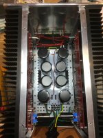
The problem I have run into is that I can't get DC offset to zero by adjusting P2 on the bias board (I'm following 6L6's procedure in the BA-3 illustrated build guide). I am measuring dc voltage between "out" on the bias board and PSU 0V (believing that this is a proxy for measuring offset between spkr in and out), one side at a time. The best I can get is 48mVDC on one board and 109mVDC on the other. All parts are per the BOM except for a 2k pot at P2.
Am I going about this correctly or am I on the wrong track?
Why might the offset be so stubbornly high?
Could one put in a higher valued pot at P2 or increase R25?
Here is a picture of the internals of one channel.
Thanks,
-Keith-
Hi,
I'm building a pair of BA3-B monoblocks (complementary output pairs, 6 pairs per channel) and setting bias and dc offset on the output section.
The input power is +/- 25.2VDC, and there is no signal input or output hooked up at the moment.
Setting bias is straightforward and currently at 0.75A measured across the 1Ω source resistor(s).
The problem I have run into is that I can't get DC offset to zero by adjusting P2 on the bias board (I'm following 6L6's procedure in the BA-3 illustrated build guide). I am measuring dc voltage between "out" on the bias board and PSU 0V (believing that this is a proxy for measuring offset between spkr in and out), one side at a time. The best I can get is 48mVDC on one board and 109mVDC on the other. All parts are per the BOM except for a 2k pot at P2.
Am I going about this correctly or am I on the wrong track?
Why might the offset be so stubbornly high?
Could one put in a higher valued pot at P2 or increase R25?
Here is a picture of the internals of one channel.
Thanks,
-Keith-
Attachments
...The best I can get is 48mVDC on one board and 109mVDC on the other. All parts are per the BOM except for a 2k pot at P2...
Measuring point is good, you don't say which way the offset is, I'll assume +.
Either increace R26 or decreace R25 - think of it as the larger the value, the further your pushing away from the supply rail.
Hmmm. Well, that is a good point. Both offsets are negative, measured with the common (black) probe on gnd, and with the red probe on “out”. P2 is turned down to about 0 Ohm, and increasing the resistance across P2 causes a larger magnitude negative offset.
Does that make sense?
Does that make sense?
Tack a 100K resistor (or thereabouts) across R26, what is the change in the output offset - from what to what?
Hi Itsmee,
Thanks for your help!
With a 100k Ohm resistor parallel to R26, the offset goes from -45mV to +1300mV.
Thanks for your help!
With a 100k Ohm resistor parallel to R26, the offset goes from -45mV to +1300mV.
I built this and had to abandon the project because the power output was so low. I am now building an Aleph 1.2, that's a real wild animal.
Too low for what ?I built this and had to abandon the project because the power output was so low. I am now building an Aleph 1.2, that's a real wild animal.
Can you please shed some light on your experience?
...-45mV to +1300mV.
 Just find the apropriate pad resistor to // R26, or increace R25.
Decided to have a go at doing my own BBA3FE a few weeks ago and it seems to be working. Need to do some final calibration to ensure that the bias is stable, but so far so good 😀
Offboard DC-blocking caps not shown 😉
Nice board.
Did you measure the offset swing before the coupling caps?
Yes, that did it. I paralleled 910k with R26 and it settles nicely in the middle of the pot range. DC offset is about 1mV and I'm sure I can tune that out after a bit of run time.
I backed off the bias to 600mA and it is now soaking, but all seems very stable
Thanks very much. 🙂
Hello ;
I've seen an earlier post that one of the members tried a Ba3B but used only one bias board for both positive and negative side of the output stage. Is this even possible?
(post 632)
There is the second more obvious issue ... the front end does not profide the + and - side of the voltage swing (but i'm not curious about that).
So my question is : for a balanced channel (+ - output stages) are necessary 2 biasing sections or one would suffice?
Last edited:

I wouldn't be caught dead in tighties ! but is not the issue here 🙂 I was just wondering (since biasing in my head simply raises the gate voltage on the power transistor's gates keeping it open and in the optimum area of conductivity awaiting the D signal)
why one would consider using just one biasing board for both polarities of the output stage?
why one would consider using just one biasing board for both polarities of the output stage?
if gates are needing only voltage bias why one would care if is provided by 1 or 2 stages.
I guess my condensed question : Is the biasing circuit actually aware of the input signal?
I guess my condensed question : Is the biasing circuit actually aware of the input signal?
well , to keep things clear , post here schmtc of OS , either SE or balanced
speaking of BA3 , not BA2 or BA1
speaking of BA3 , not BA2 or BA1
For a BTL (bridge tied load) two bias boards will be required (one per output stage).
post 632 shows a '6 deep' single output stage
post 632 shows a '6 deep' single output stage
Last edited:
Yes, both output sections need their bias boards. They won't bias without it. So for a monoblock, there will be one front-end and two output sections w/bias boards.
Bias is straightforward - set the bias of the front-end just like a F5. Once that's set, you don't have to worry about it again. Then set the bias of each output section, with it's own bias pot, and own offset pot. Because this is not a DC-coupled design, each section will set individually from the others.
Global DC offset will be bias balance between the two halfs (Phases). It will make more sense when you are doing it.
Possible to do a DC coupled?
- Home
- Amplifiers
- Pass Labs
- Burning Amp BA-3b (Balanced)