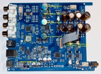
Finneybear excellent post #113 is already very clear on what to replace at the dac's output. All the parts that needs replace are labelled. You can skip the opamp replacement as it is a bit more difficult to desolder and opa1612 is already fairly good. The most impact will likely be the removal of the tantalum coupling cap at ak4493 dac output and replace with a zero ohm resistor (or straight wire) plus the surrounding filter parts.
Thank you phase and ChuckT. I have documented all of the specific modifications and copied every picture I could find.
My next step is to study all of the above and see if I can identify the components to be replaced and the EXACT component to replace it with.
I'll keep working on this as time permits.
EDIT: I did find a post on another forum where cidious put all of his mods with pictures into one post.
My next step is to study all of the above and see if I can identify the components to be replaced and the EXACT component to replace it with.
I'll keep working on this as time permits.
EDIT: I did find a post on another forum where cidious put all of his mods with pictures into one post.
Last edited:
.........
EDIT: I did find a post on another forum where cidious put all of his mods with pictures into one post.
I did find a post on another forum where cidious put all of his mods with pictures into one post.
please can you post the link here: learning is mandatory 😉
chris
I did find a post on another forum where cidious put all of his mods with pictures into one post.
please can you post the link here: learning is mandatory 😉
chris
TOPPING DX3 Pro | Page 8 | Headphone Reviews and Discussion - Head-Fi.org
I hope this is permitted.
Then can you point out the implied measurable distortion this “delayed” feedback would produce?
Let's start with a simple scenario. Distortion happens when the input signal to an amp changes. Since signal change causes distortion, the distortion will follow the 2nd order of the signal, this is the 2nd harmony distortion.
Now if you add feedback to the amp, the 2nd harmony distortion will go to the input side of the amp. The change of 2nd harmony distortion will in turn, create 3rd harmony distortion on the output. In, turn, this loop will go recursively, you will start to see 4th, 5th, etc, harmony distortions.
When you feed the amp to next stage, you will start to see more 2nd, 3rd, 4th, etc, distortions.
This is why you will see all of the harmony distortions in a FFT chart.
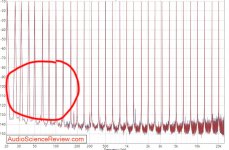
Unfortunately, all amp outputs have phase shift. When the negative feedback has phase shift, the error correction will hit the wrong spot, then in turn, create funny shape distortion *spikes*. Those spikes still have the same base frequency yet due to their funny shape, will contain non-harmonic frequency components. When you look at the FFT chart, you will start to see those frequencies show up, some are little spikes around the base frequency.
In 80's, Japan made a lot of super low distortion amps. Most of them did not sound good, especially for those with floating bias ones. At that time, spectrum analyzers were still not widely used to analyze the frequency components of distortions hence engineers did not have clear clues about what's going on. People started to blame NFB as the culprit hence no NFB machines became a fashion. There were also arguments about global NFB vs local NFB. Another gang of thinking was to build super fast, high slew rate machines hence the birth of Leech.
What many of us do is to google the numbers printed on all those parts and see what they are and then find out what they do. Then you can have a better idea of the architecture, the power supply will be identified easier that way, as well as everything else.
I will often take a picture of the board, and make notes or point out certain things for reference.
The charge pump is there to make it easier to have a dual rail supply from a single (battery) supply as is typically used in a phone. Other chips do this for the output stage when it is contained within the chip, I suspect that’s the same with the cs chip.
Well, I was surprised when a friend told me the new CS43198 sounded very good! Then after I thought about the whole thing over again, things start to make sense to me.
CS43198 is the first high end all in one design DAC chip. It is built mainly for portable audio devices/cell phones, etc. It has everything inside, even headphone detection. It has PLL based jitter removal, configurable digital filter, and only needs 1.8V power supply, etc.
The charge pump allows it to output 5V signal, and since its output is H-calss based, the LPF is given hence no need for external LPF. A CS43198 with output buffer, that's all what you need.
Is the H class output bad? Not really. Remember that DSD itself is PWM as well. If DSD could sound good, H class can sound good, too, as far as the switching frequency is high enough. The beauty of this architecture is that, the H class output will remove the need of external LPF hence there will be no active I/V, no active LPF involved. No active LPF means no NFB, the whole signal chain now has no NFB. The only NFB happens in the digital filter inside CS43198, in the digital domain. In the analog domain, it's a simple straight path, no NFB. Definitely this will give a very unique sound to CS43198, and I am not surprised it can sound good now. What a brilliant design idea!
Finneybear excellent post #113 is already very clear on what to replace at the dac's output. All the parts that needs replace are labelled. You can skip the opamp replacement as it is a bit more difficult to desolder and opa1612 is already fairly good. The most impact will likely be the removal of the tantalum coupling cap at ak4493 dac output and replace with a zero ohm resistor (or straight wire) plus the surrounding filter parts.
Actually you can easily remove OPA1612 with low temp solder such as this one:
Chip Quik - ChipQuik Alloy (10)
Still more components to replace. Please see the marks in the attached pic.
Attachments
Thank you phase and ChuckT. I have documented all of the specific modifications and copied every picture I could find.
My next step is to study all of the above and see if I can identify the components to be replaced and the EXACT component to replace it with.
I'll keep working on this as time permits.
EDIT: I did find a post on another forum where cidious put all of his mods with pictures into one post.
I have a BOM under mouser.com. Want me to share the BOM here?
I have a BOM under mouser.com. Want me to share the BOM here?
Please!!!!!! I am always searching for BOMs because it helps so much.
Also, I have a hot air SMD rework station. Best $29 I ever spent. I built a Sjostrom QRV-08 so I also have a lot of practice with SMDs
Last edited:
The journey has begun. I just ordered a DX3 Pro from Blinq. $173, with -10% coupon, so not too bad.
I'm sure I'll be back to this thread with many questions.
The first. Is a better power supply essential?
If so, can I combine both side of a +- 15V supply (from one of my dacs), or is it better to have a linear PS?
If linear is recommended I would appreciate link to Chinese DIY kit if anyone has one.
finneybear, looking forward to BOM if you can manage it.
Last edited:
The journey has begun. I just ordered a DX3 Pro from Blinq. $173, with -10% coupon, so not too bad.
I'm sure I'll be back to this thread with many questions.
The first. Is a better power supply essential?
If so, can I combine both side of a +- 15V supply (from one of my dacs), or is it better to have a linear PS?
If linear is recommended I would appreciate link to Chinese DIY kit if anyone has one.
finneybear, looking forward to BOM if you can manage it.
Here is the shared shopping cart at mouser.com
Mouser Electronics
Attached is the BOM in Excel/ZIP format. Part locations are shown in the comment column.
Standard disclaimer - I am not responsible for any damage done to the machine as well as any hazard brought up by the mod. There is no guarantee the change on sound quality will meet your expectation either. In other words, you are doing the mod at your own risk! 😀
The stock power supply will work fine. Just remember to connect the power supply to the machine first before you plug it to the power outlet. Sure, a good linear power supply with at least 1.5A current will definitely help.
Some mod tips:
. OP can be easily removed by low temp alloy solder as I mentioned above.
. Small caps and resistors can be removed by hot tweezer with rework station. If not available, the low temp alloy works, too.
. SMD e-capacitors can be easily removed by the twist and turn trick with a needle plier. You can search youtube.com for a demo.
. After the SMD parts are removed, clean up the solder pads with solder wick.
. You will need a good temp controlled solder station with small tip for the soldering work.
. To solder the small SMD parts, the reflow method can be tricky to do. I'd suggest you soldering the components directly with solder paste.
. I'd suggest you get solder paste with high silver content (3.0 Ag). Plenty to choose on eBay and mouser.com. I recommend the Chip Quik TS391SNL solder paste in syringe tube. It is thermally stable so it can last for a long time. One 15 gram tube is enough for doing many projects to come.
. Again, check out youtube on how to apply solder paste. The trick is dont apply too much solder paste. One tiny droplet is more than enough.
. Long sharp tip tweezer is required to do precision placement of tiny SMD parts. Be sure to practice this on an old graphics card or something similar first.
. SMD e-caps can be soldered with the heat and slide trick. Check youtube for details. Use lead base solder for its low melting point. Non-leaded based solder is very hard to work with here.
Attachments
Let's start with a simple scenario. Distortion happens when the input signal to an amp changes. Since signal change causes distortion, the distortion will follow the 2nd order of the signal, this is the 2nd harmony distortion.
Now if you add feedback to the amp, the 2nd harmony distortion will go to the input side of the amp. The change of 2nd harmony distortion will in turn, create 3rd harmony distortion on the output. In, turn, this loop will go recursively, you will start to see 4th, 5th, etc, harmony distortions.
When you feed the amp to next stage, you will start to see more 2nd, 3rd, 4th, etc, distortions.
This is why you will see all of the harmony distortions in a FFT chart.
Unfortunately, all amp outputs have phase shift. When the negative feedback has phase shift, the error correction will hit the wrong spot, then in turn, create funny shape distortion *spikes*. Those spikes still have the same base frequency yet due to their funny shape, will contain non-harmonic frequency components. When you look at the FFT chart, you will start to see those frequencies show up, some are little spikes around the base frequency.
In 80's, Japan made a lot of super low distortion amps. Most of them did not sound good, especially for those with floating bias ones. At that time, spectrum analyzers were still not widely used to analyze the frequency components of distortions hence engineers did not have clear clues about what's going on. People started to blame NFB as the culprit hence no NFB machines became a fashion. There were also arguments about global NFB vs local NFB. Another gang of thinking was to build super fast, high slew rate machines hence the birth of Leech.
The OPA1612 has so much loop gain that these other terms are driven to nothing. See Bruno Putzeys article "The F-word". What you are talking about is termed re-entrant distortion.
You still didn't explain why this distortion wouldn't show up in any measurements 😕. The datasheet has FFTs and sweeps.
Apologies for sidetracking the thread.
Last edited:
The OPA1612 has so much loop gain that these other terms are driven to nothing. See Bruno Putzeys article "The F-word". What you are talking about is termed re-entrant distortion.
You still didn't explain why this distortion wouldn't show up in any measurements 😕. The datasheet has FFTs and sweeps.
Apologies for sidetracking the thread.
Obviously you have no idea about what I was talking about. I am even not sure how you read the datasheet.
The FFTs I meant has to be done in a closed loop. There will be individual FFT for each base frequency, say, 400Hz, 1KHz, etc. No OP datasheet would ever published this kind of FFT charts. They are application based.
OP works with very high open loop gain. OPA1612 has an open loop gain around 130dB. A lot of OPs have roughly the same open loop gain. Not sure what you meant OPA1612 has very high open loop gain. Cant see anything peculiar about it. OP has to be used with closed loop and here you get the "re-entrant distortion" (in your term) partly due to phase shift.
I have several friends who have designed OP ICs. It's amusing to see people creating all kinds of myths around OPs.
I'm pretty sure you're creating the myths here (mid bass thin of OPA1612 - lol). The datasheet has closed loop distortion vs frequency sweeps with specified load and gain. You should try actually reading it - see Figure 7. If there are distortion products that exist - above the noise floor - they would show up. I do not know how YOU are reading the datasheet. I don't care if your friends design ICs, it doesn't mean you are right.
Of course every op-amp has high OLG. If you bothered to read Bruno's analysis you will see that the new distortion products show up at moderate levels of feedback and will be reduced with more feedback.
Please, show me your mythical LF distortion with an OPA1612. I will wait for the FFT.
Why don't you go put this into SPICE and see what you get? I know what you won't see...
Last edited:
I'm pretty sure you're creating the myths here (mid bass thin of OPA1612 - lol). The datasheet has closed loop distortion vs frequency sweeps with specified load and gain. You should try actually reading it - see Figure 7. If there are distortion products that exist - above the noise floor - they would show up. I do not know how YOU are reading the datasheet. I don't care if your friends design ICs, it doesn't mean you are right.
Of course every op-amp has high OLG. If you bothered to read Bruno's analysis you will see that the new distortion products show up at moderate levels of feedback and will be reduced with more feedback.
Please, show me your mythical LF distortion with an OPA1612. I will wait for the FFT.
Your mentioning of Figure 7 only confirms my statement that you have no idea about what I was talking about. Please see the attached 1KHz FFT chart. This is the FFT I was looking at. You also need to look at charts such as 100Hz, 400Hz, etc.
As for Bruce's article. He may be a class D master but he did not know everything inside an OP. What he talked about are just very basic and ideal stuff. For instance, the key is not the difference between fast or slow amps. It is the speed of an amp may change among different frequencies.
People all know what he's trying to say yet there are a lot of things much deeper than those. That's where people start to argue about global NFB vs local NFB, and amp speed, etc. Not this simple.. consider they are all seasoned circuit designers.
Attachments
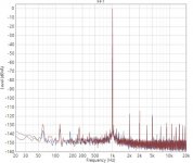
Your mentioning of Figure 7 only confirms my statement that you have no idea about what I was talking about. Please see the attached 1KHz FFT chart. This is the FFT I was looking at. You also need to look at charts such as 100Hz, 400Hz, etc.
As for Bruce's article. He may be a class D master but he did not know everything inside an OP. What he talked about are just very basic and ideal stuff. For instance, the key is not the difference between fast or slow amps. It is the speed of an amp may change among different frequencies.
People all know what he's trying to say yet there are a lot of things much deeper than those. That's where people start to argue about global NFB vs local NFB, and amp speed, etc. Not this simple.. consider they are all seasoned circuit designers.
How do you think a THD vs frequency plot is obtained...
I do not think you understand what you read, sorry.
How do you think a THD vs frequency plot is obtained...
I do not think you understand what you read, sorry.
Nope. total THD numbers give you very little of the whole story. Do you know how total THD number is calculated? 😀
Nope. total THD numbers give you very little of the whole story. Do you know how total THD number is calculated? 😀
You're still not showing anything of use or conclusive. You can continue with your LF distortion "slow feedback" myth.
- Home
- Source & Line
- Digital Line Level
- [Modding] Topping DX3 Pro