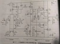
About Chapter 17, Class A Power Amplifier, Figure 17.19. Why is it wrong to connect C5 to the circuit in the simulation? Who can tell the effect of C5?
In fact, I only want to be a Class A, Figure 17.7, it can't be used. It seems that his Class A quiescent current control, I don't understand, who can help me explain.
In fact, I only want to be a Class A, Figure 17.7, it can't be used. It seems that his Class A quiescent current control, I don't understand, who can help me explain.
Last edited:
Analyze Class A quiescent current control. Thank you! !
Attachments

Last edited:
If you make a class A according to Figure 17.7, can you? Figure 17.19 is a class A and class AB class B. I only want class A.
Last edited:
You can make class A with fig 17.7. To set the class A current, you must set Vref = Iq * (2*Re). So, for example, if you want say 1 Amp standing current, set Vref to 0.44V
C5 is a boot strap capacitor and gives you more voltage swing.
C5 is a boot strap capacitor and gives you more voltage swing.
Last edited:
hi
The bias circuit in Self's class-A amp is in strong contradiction to the words he wrote regarding bias spreaders in general. He showed that the CFP bias spreader was superior even to his resistor-enhanced single-BJT circuit, but stated he did not want to risk failure of the circuit by adding more parts.
Doctors take a hypacratic oath; maybe engineers take a hypocritical oath?
The diodes across the feedback shunt cap are to protect the cap in case the output fails shorted to either rail. Feedback at DC is unity-gain (1), so the cap would theoretically be subject to the full rail voltage.
Last edited:
Why the aggression? What's wrong with showing something is technically better but deciding against it for other reasons? It's something a real designer does all the time.
You may not agree but that doesn't mean you should insult and imply hypocrisy.
Jan
You may not agree but that doesn't mean you should insult and imply hypocrisy.
Jan
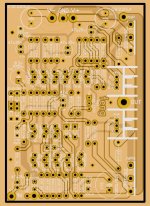
I don't know the actual effect of this circuit? I have drawn the PCB, please correct me. This circuit has many very old triodes. Which new transistors should be used for replacement?
Attachments
Last edited:
Are you expecting us to derive a circuit from a PCB layout and then comment on the used tubes??
Jan
Jan
Are you expecting us to derive a circuit from a PCB layout and then comment on the used tubes??
Jan
I think he means transistors.😀
Yes, I mean a transistor. The transistor type of the original circuit is too old. Can it be replaced by modern transistors?I think he means transistors.😀
Yes, I mean a transistor. The transistor type of the original circuit is too old. Can it be replaced by modern transistors?
You can replaced with new modern but you have to know what to use.
All the transistors on this board are still available AFAICT. It would probably be wise to replace the commonly counterfeited and long EOL 2SC3281/2SA1302 with the in-production MJL3281/1302 or similar. MJE340/350 are still active. MPSA06/56 also are, but do not seem to be made in large numbers, making them a bit more expensive than some other TO-92s (2N5550 may be a suitable but somewhat less good replacement).
Question on a typical LTP (Schematic snip from a Heathkit AR-1500).
It can be seen that the total LTP emitter current is nominally 4 mA. Yet, with a 680 ohm collector resistor, the static current in the Q1 side will settle in at about 1 mA, leaving 3 mA for the Q2 side.
This is obviously an unbalanced condition. It seems the general consensus that matching the input devices is important for lowest distortion and to minimize output offset. With the static imbalance apparently 'designed in', there is no way one is going to get the output offset down to a reasonable value without injecting current into one of the inputs from an outside source.
I've seen this in amplifiers other than just the Heathkit. Why are amplifiers sometimes designed this way with the intrinsic imbalance?
Attachments

I think you are wrong. Through Q1 and Q2 goes the same current of 2 mA each. Through R4 goes 1 mA and the other 1 mA goes from the base of Q3 to the emittor of Q3.
But I agree this is not a good design.
But I agree this is not a good design.
Didn't show the full schematic, but the collector current source for the VAS is less than 10 mA. Assuming a reasonable hfe of 50 for the VAS, that means it needs 0.2 mA of base current.
So the LTP has 1.2 mA in the Q1 branch, and 2.8 mA in the Q2 branch. Still considerably unbalanced by design.
So the LTP has 1.2 mA in the Q1 branch, and 2.8 mA in the Q2 branch. Still considerably unbalanced by design.
Last edited:
Indeed it needs at least 0,2 mA of base current but the base current can be much higher even with a collector current of 0,2 mA. The base-emittor of Q3 functions more as a diode.
Where is your circuit diagram coming from?Question on a typical LTP (Schematic snip from a Heathkit AR-1500).
It can be seen that the total LTP emitter current is nominally 4 mA. Yet, with a 680 ohm collector resistor, the static current in the Q1 side will settle in at about 1 mA, leaving 3 mA for the Q2 side.
This is obviously an unbalanced condition. It seems the general consensus that matching the input devices is important for lowest distortion and to minimize output offset. With the static imbalance apparently 'designed in', there is no way one is going to get the output offset down to a reasonable value without injecting current into one of the inputs from an outside source.
I've seen this in amplifiers other than just the Heathkit. Why are amplifiers sometimes designed this way with the intrinsic imbalance?
- Status
- Not open for further replies.
- Home
- Amplifiers
- Solid State
- Douglas Self Sixth Edition