Thx for explaining bButcher, I'm just hobbyist so I'm just starting to learn electronics (I'm quite technical but never did soldiering) thx to ppl like you I'm motivated to learn a bit
I am also building single voltage kit for 24V output.
If you take 24VAC output transformer, i'll recommend take a filter capacitor rated for at least 40V instead of stock 6800×35V. I've ordered 6800×50V with ⌀25mm and height 40mm (capacitor need to be a ⌀25mm to fit to the board).DC voltage after rectifier is 25.2V, just enough to keep output regulated, so for your application I will recommend a 24VAC output transformer.
Regarding to 1.5A limitation, with further investigation one can see it is because D102, D103 serve as limiter, so the circuit is designed to maximally provide 1.5A output current.
With D102 & D103 removed and continue the simulation, now the circuit can provide up to 2.5A and fail again before 3A.

Thanks for your insights bButcher - greatly appreciated. When you remove D102 and D103, do you suggest a link wire? Or simple removal?
I notice another post mentions "the current limiting resistors on my board are 2.2 Ohm". What are your thoughts here?
Thanks again,
narla
@Narla
(1) Just removal. Since D102 and D103 are in series, removal of anyone will do the trick.
(2) R107 also serves as current limiter, it is used to turn on Q103 to drain base current from bypass transistor Q104 when current through it exceed 0.6V/R107, 2.2 ohm will set the limiting current to ~270mA. In my module, it is 0.1 ohm, which set limit current @6A.
(3) So yes, you also have to check R107 to see if it is appropriate. e.g if you want to supply maximally 2A from the module, other than removal of diodes, change R107 to 0.3 ohm/1W too.
Sadly this product is not available anymore on Audiophonics...
If you don't mind eBay, it's available there - and at a lower price.
Or buy two single supply boards at lower price and bigger heat sink.
Linear Power Supply board MJE15034G Low noise 5V a 24V 2A - Audiophonics
Linear Power Supply board MJE15034G Low noise 5V a 24V 2A - Audiophonics
Regarding to 1.5A limitation, with further investigation one can see it is because D102, D103 serve as limiter, so the circuit is designed to maximally provide 1.5A output current.
If you look at the circuit, there is a current limiting resistor R407 in the return line of 0.1 ohms, and a current limiter transistor Q103 that siphons off base drive for the pass transistor when the current reaches about 6A.
The two diodes limit the base current into the pass device but because the ratio collector current to base current of the pass device can vary all over the place, it doesn't make for a dependable current limiter. It may be 2A but then again 5A or 1A with another pass device. The diodes mainly limit current into the pass transistor base and also protect Q105 of course.
The better way is to set R407 for the wanted current limit, that is better defined and dependable, limiting current when the voltage across R407 reaches about 0.65V.
BTW R109 and R111 modify that current limit somewhat to make it limit at lower currents when the Vce of Q404 is high. A good precaution.
Jan
Last edited:
Thanks Jan for clarification. Yes, the original value of R107 is 1.65 ohm which will set the current limit @ 400mA, way ahead of D102, and D103 start to kick in.
BTW, I'm waiting for the delivery of AD817 and LM336-2.5, so I can finish my 5V super regulator project. Hopefully within weeks I can compare how these two different design perform in my setup.
BTW, I'm waiting for the delivery of AD817 and LM336-2.5, so I can finish my 5V super regulator project. Hopefully within weeks I can compare how these two different design perform in my setup.
Yes I think this supply should be good for an amp or two? Like 0.33 ohms for the CL R? More than the Jung/Didden superreg is rated for.
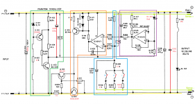
I noticed that there are wire stubs in the drawing on the inputs of the ref opamp, were there opposite diodes there for protection? Also on the error amp; often horrible things happen at switch on and seitch off.
BTW Good idea to indicate the various function with colored boxes, helps making sense of things.
Jan
Thanks for the technical advice chaps - very enlightening!
To clarify: To enable 2A, may be best to replace R407. Do you have a recommended value?
Also mentioned was R109 and R111 as a precaution. Any values here?
The biggest improvement I've made to date is to replace the Nover 6800uf cap with a Mundorf Mylytic. I also replaced the smaller electrolytic caps with Nichicon Fine Gold.
I look forward to the results of AD817 and LM336-2.5 bButcher!
BTW, I run 3 x Studer 900s in my system - with excellent results in all cases.
Thanks again,
Narla
To clarify: To enable 2A, may be best to replace R407. Do you have a recommended value?
The value of R107 (not 407) is approximately 0.65/I, where I is the required current at which it will shut off.
Hence for 2A you will need a resistor of 0.33 Ohms.
Should be the same for 12V, but check if the heatsink is capable.
Last edited:
@Narla
(1)
Going back to the original Studer 900 circuit might give a little more inside how R107, R109 & R111 work togather to limit the current & power consumption of
Q104 & load.
Vbe_Q103 = R107||R108 * I + Vce_Q104 * 180/(22k+180), where R107||R108 = 1.65
Q103 will be turned on when Vbe_Q103 = 0.65V, or I_limit = (0.65 - Vce_Q104 * 180/(22k+180))/1.65
Power comsumption of Q104, P_Q104 = Vce_Q104 * I_limit = Vce_Q104 * (0.65 - Vce_Q104 * 180/(22k+180))/1.65
The maximal power comsumption occur when 2 * Vce_Q104 * 180 / (22k + 180) = 0.65, or Vce_Q104 = 0.65 * (22k + 180)/(180 * 2) = 40.047V
Below list some values for reference:
---------------------------------------
Vce_Q104.I_limit............P_Q104......P_load = (52V - Vce_Q104) * I_limit when Vin = 52VDC
---------------------------------------
0_______ 394mA_______0W
4_______374mA_______1.497W___18W (48V)
5_______369mA_______1.847W
7_______360mA_______2.517W
10______345mA_______3.448W
28______256mA_______7.174W___6W (24V)
35______222mA_______7.763W
40.047___197mA_______7.888W___2.4W (12V)
45______173mA_______7.767W
50______148mA_______7.401W
65_______74mA_______4.826W
80.094_____0mA_______0W
----------------------------------------
Here I assume fixed Vin = 52VDC, and a switch change output between 12, 24 & 48 volts.
So the original circuit is designed to provide 200mA@12V (2.4W), 250mA@24V (6W), 370mA@48V (18W) at load, and also limit power consumption <8W at pass transistor Q104.
If you don't want current limit vary with Vce, the easiest way is to remove R111 and short R109, then R107 will simply be 0.65V/2A = 0.33 ohm regardless of Vce.
then choose a heat sink big enough for worst case Vce value.
If you want to keep R109 & R111 intact, then use worse case Vce to calculate the needed R107 value. e.g. if biggest Vce is 7V then R107 = [0.65-7*180/(22k
+180)]/2A = 0.3 ohm.
(2) It is not directly related, but Vce will depend on AC input & V_load.
Vin_DC = Vin_AC * sqrt(2) - 2*sqrt(2)*Veff
Vin_DC = V_load + Vce + I_load*R107 ~= V_load + Vce
=> Vce ~= Vin_AC * sqrt(2) - 2*sqrt(2)*Veff - V_load
Now in worst case, Vin_AC = Nominal_AC * Lr * Tr, where Lr is line regulation & Tr is transformer regulation
assume Lr = 1.1 (230V -> 253V) and Tr is 5% @2A then Vin_AC = 12V * 1.1 * 1.05 = 13.86VAC
assume Veff = 1V @ 2A, then Vin_DC = 13.86 * sqrt(2) - 2*sqrt(2)*1 = 16.77
lets say your intended dc out value V_load is 10V, then worst case Vce will be 6.77V
It is very complicated to calculate Veff. Under light load it will approach diode forward voltage, but will increase if load increase because of diode bulk
internal resistance, usually I just measure it.
Using Tslema 35VA transformer Veff ~= 0.7 @0.5A & ~= 0.87 @1A.
Last edited:
@Jan
You can check the original extract from Studer 900 circuit from post #39, "regulator studer900.pdf". I modified that circuit to reflect where the kit I bought is different from the original design. The wire stubs is deliberately left there to indicate removed parts. The missed part in the ref op is a 22p cap.
One thing I like about this design beside its potential to provide higher current is separating op power supply from the output voltage, so for 5V output it still can use 10V op. I know it might not perform at the same level as superreg which uses clean output voltage to power op and related circuit, but it is very convenient to design this way.
Last edited:
Yes, agreed, the 'floating' opamp is needed to be able to easily switch output voltage without having to redo other stuff.
Compensation cap, yeah that makes sense too.
BTW Why was this output variable? Was it supposed to supply different pieces of equipment, or was it related to tape speed switching?
Jan
Compensation cap, yeah that makes sense too.
BTW Why was this output variable? Was it supposed to supply different pieces of equipment, or was it related to tape speed switching?
Jan
I remember someone mentioned this circuit is supposed to be used to power active mic, but usually phantom power is 48V, maybe some mic need 24V or 12V too. Not familiar with different mic technology, just guessing.
O.K from Wikipedia "phantom power" standard (IEC 61938:2013) do have three variations "P12, P24 and P48", but standard also recommends 48V for new system, so almost all current mixing console only provide 48V phantom power.
For those with experience, the attached diagram show you how to modify the board to do remote sensing. Also you can power the reference led with clean output ground instead of dirtier 10V virtual ground (~0.4mV ripple @ 0.5A load).
For those with experience, the attached diagram show you how to modify the board to do remote sensing. Also you can power the reference led with clean output ground instead of dirtier 10V virtual ground (~0.4mV ripple @ 0.5A load).
Attachments
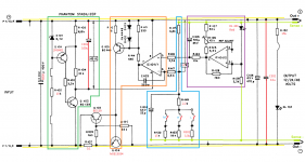
Yes those are worthwhile changes!
Do try it out because in my experience, remote sensing can have stability implications from the inductance in the sense lines, depending on length.
What you also might want to do is use a screened cable for the sense lines to prevent hum/EMI pickup, again depending on length.
Jan
Do try it out because in my experience, remote sensing can have stability implications from the inductance in the sense lines, depending on length.
What you also might want to do is use a screened cable for the sense lines to prevent hum/EMI pickup, again depending on length.
Jan
- Home
- Amplifiers
- Power Supplies
- low noise Pre-Amp / DAC power supply MJE15034 TL072 Regulator based on STUDER 900