@Mark. I don't know whether you recall, but some time ago we were discussing the reproduction of saxophone and how it can at times sound synthesized. I mentioned a track which sprang to mind but couldn't recall what it was, anyway, here it is, it's primarily the opening sequence that I thought you might find interesting and the vibrato adds to the effect. YouTube
... here it is, it's primarily the opening sequence that I thought you might find interesting and the vibrato adds to the effect.
Video unavailable
This video contains content from UMG, who has blocked it in your country on copyright grounds.
I am about to surprise you... 🙂
This is all easily measurable, many have done it.
You keep trying to say Pavel agrees with you, he does not. He already restated that the amplifier had nothing to do with the distortion he measured it was purely the known physics of the speaker. Referencing 1970's vintage class A/B solid state amplifier technology with 1MHz ft transistors biased at a few mA to save on heatsink area is a waste of time. You can easily find an amp today that will not contribute any distortion. BTW a bad class A/B amplifier has distortion with a purely resistive load, making the speaker look like 8 Ohms at 0 phase 20 to 20k will not fix it.
As you yourself argued in dozen's of posts your Elsinore speaker is not based on current drive. Maybe someone here can comment on any expected distortion measurements of it. There are literally dozens (maybe>100) of published studies on the distortion of the motor/suspension in a dynamic speaker, unfortunately many are behind the AES paywall. Are you or are you not claiming they are wrong or missing something? Finally I've said before you could be doing something of value but you present it in a confused manner so few can follow.
BTW the same (distortion characteristics are different) holds for electrostatic transducers when you drive them in constant charge or constant voltage mode.
Guys, please have a look at the Elsinore xover here:
Elsinore Speakers DIY

Plse pay particular attention to the loop consisting of C1, L3 and C2. The depth of the short circuit this produces around 2.7 kHz will only be determined by the quality of the components used. It is bound to smoke amps.
Now please have a look at the graph on the linked site titled "Actually measured impedance and electrical phase angle". How can this ever be a measured result of a loudspeaker containing such a xover?
As to Scotts question: I would expect distortion to be pretty much like these drivers would produce on their own. With possibly a bump around 2.7 kHz if an amp can't deal with very low impedances.
Besides this, a major issue I see with these speakers is that they are bound to suffer from extreme beaming since the four mid bass drivers are placed in a large array with shallow xover curves. The mid to high transition region will be particularly exciting, beam wise, because of the large distances between the top three drivers in a d'Appolito configuration. I'd love to see horizontal and especially vertical polars.
Elsinore Speakers DIY
Plse pay particular attention to the loop consisting of C1, L3 and C2. The depth of the short circuit this produces around 2.7 kHz will only be determined by the quality of the components used. It is bound to smoke amps.
Now please have a look at the graph on the linked site titled "Actually measured impedance and electrical phase angle". How can this ever be a measured result of a loudspeaker containing such a xover?
As to Scotts question: I would expect distortion to be pretty much like these drivers would produce on their own. With possibly a bump around 2.7 kHz if an amp can't deal with very low impedances.
Besides this, a major issue I see with these speakers is that they are bound to suffer from extreme beaming since the four mid bass drivers are placed in a large array with shallow xover curves. The mid to high transition region will be particularly exciting, beam wise, because of the large distances between the top three drivers in a d'Appolito configuration. I'd love to see horizontal and especially vertical polars.
Last edited:
HPR is so cool..I work with a lot of grown up nerds, one of them still plays with multi-stage model rockets. His latest one will require a special permit and a trip to the desert, a fairly high altitude model rocket.
He gets along with everyone else as far as I can tell though.
Once you go past E engines (IIRC), HPR rules are you have to qualify in order to buy and use them. IIRC, you have to be able to launch one rocket three times (the same rocket) under supervision. This is to verify that you can launch and recover successfully.
The hybrid motors, liquid plus solid, run up to M and N last I saw, perhaps a P was being done as well. (specific impulse doubled with each letter). Operation above mach 1 also change the strength requirements and analysis complexity, as nose cone and fin leading edges change.
Launch get-togethers require FAA permissions beyond a specific altitude.
John
There are literally dozens (maybe>100) of published studies on the distortion of the motor/suspension in a dynamic speaker, unfortunately many are behind the AES paywall.
Remember a while ago, someone posted a paper with the magnet structure made of 3 neo rings with opposite polarities? I don't recall if the author mentioned using the return path flux as a brake to over-excursion?
Well, I just saw a video where a magnetizer was producing opposite polarity zones in a single piece of neo.
Meaning, it is totally possible to make the magnet assembly as a one piece structure, and it doesn't require the suspension springiness of conventional speakers.
John
Meaning, it is totally possible to make the magnet assembly as a one piece structure, and it doesn't require the suspension springiness of conventional speakers.
An untethered radiating surface? That sounds interesting, but I think we are talking more basic issues here, I don't think Joe's crossover eliminates excursion limits that would be interesting.
Guys, please have a look at the Elsinore xover here:
Elsinore Speakers DIY
View attachment 736500
Plse pay particular attention to the loop consisting of C1, L3 and C2. The depth of the short circuit this produces around 2.7 kHz will only be determined by the quality of the components used. It is bound to smoke amps.
Now please have a look at the graph on the linked site titled "Actually measured impedance and electrical phase angle". How can this ever be a measured result of a loudspeaker containing such a xover?
C2>>C1 so C1 is the one that matters. A series resonator creates an impedance notch because the voltage at the junction of the C and L is boosted above the level of the input voltage in opposite phase (which is a mode of destruction in PSU LC filters and wherever else they are used). The impedance at that point is very high at the resonant frequency. Thus a resistive load at this point has a dramatic effect on the Q of the resonance. If the load is equal to the characteristic impedance of of the LC, then there is no resonance.
Most likely that is the case as otherwise, the output of the LC network would be a spike at the resonant frequency.
I don't think this crossover is dangerous, although if the tweeter goes open perhaps it could be.
Last edited:
A series resonator creates an impedance notch because the voltage at the junction of the C and L is boosted above the level of the input voltage in opposite phase (which is a mode of destruction in PSU LC filters and wherever else they are used).
That's a very strange way of looking at cause and effect. A series LC has a notch because Ls + 1/Cs = 0 at resonance. The Q is limited by any and all dissipative losses. The 1.8uF at 2.7kHz would be ~32 Ohms at 90 degrees probably not fatal.
That's a very strange way of looking at cause and effect.
Granted.
A series LC has a notch because Ls + 1/Cs = 0 at resonance.
True, but this is misleadingly terse in context. The level increase at the LC junction is always attendant with the impedance notch. You don't get one without the other. This kind of working knowledge is useful, but perhaps the way I presented it is strange.
If you think the same way as others do, you repeat their mistakes. So I am not too worried if it is strange, as long as it is correct. But I certainly don't want to confuse anyone, so don't let me get away with it if I am.
The Q is limited by any and all dissipative losses. The 1.8uF at 2.7kHz would be ~32 Ohms at 90 degrees probably not fatal.
That's just the capacitive reactance, Vacuphile was worried about the resonance which, if the tweeter went open would be a dead short plus the inductor and speaker cable resistance. But this would be true for many crossovers currently in use.
Last edited:
My mention has nothing to do with Joe's stuff, rather it is w/r to Richard's desire to make drivers more linear.An untethered radiating surface? That sounds interesting, but I think we are talking more basic issues here, I don't think Joe's crossover eliminates excursion limits that would be interesting.
If the suspension is not pulling duty as a hard stop for excursion, it wouldn't need to be as strong. It would only need to keep the coil and cone centered, with minimal need to center front to back.
John
If you think the same way as others do, you repeat their mistakes.
Whatever works for you is fine. Given simply a resonant frequency there are literally infinite combinations of L and C but if one looks at the reactive impedance vs. the resistive loss you come up with a narrower range of values that make sense.
There are lots of cute passive circuits that give voltage gain but none can give power gain.
Last edited:
My mention has nothing to do with Joe's stuff, rather it is w/r to Richard's desire to make drivers more linear.
I understand if you don't want to chime in on the Joe stuff, there is plenty that could be done up front on the driver that would probably be more beneficial.
If you think the same way as others do, you repeat their mistakes.
Hmm, I might be a counterexample. I personally have had a lot of success, and made quite a comfortable living, thinking the same way as Pierre-Simon Laplace, Lawrence J. Giacoletto, Lawrence J. Nagel, Paul Gray, Jim Roberge, Barrie Gilbert, Norman Nise, Dick Foss, Ted Kamins, Jack Mize, Ken Thompson, and a host of others. Their ideas, their methods of analysis, and the way they thought about problems were amazingly helpful. At least, they were to me.
Guys, please have a look at the Elsinore xover here:
Plse pay particular attention to the loop consisting of C1, L3 and C2. The depth of the short circuit this produces around 2.7 kHz will only be determined by the quality of the components used. It is bound to smoke amps.
Hey Vac,
Not sure about smokin' amps but I think you've been smokin' too much of that Amsterdamsky coffee shop weed. 🙂
For the tweeter network, which you are referring to, at 2700Hz I get about 25 ohms with a 6 ohm resistive tweeter load.
T
Guys, please have a look at the Elsinore xover here:
Elsinore Speakers DIY
Besides this, a major issue I see with these speakers is that they are bound to suffer from extreme beaming since the four mid bass drivers are placed in a large array with shallow xover curves. The mid to high transition region will be particularly exciting, beam wise, because of the large distances between the top three drivers in a d'Appolito configuration. I'd love to see horizontal and especially vertical polars.
Mid Bass speakers 3 / 4 won't beam, they are crossed pretty low, from the look of it around 600 or so.
MB 1 and 2 are crossed pretty high. I'm not familiar with these drivers HF performance, maybe Joe can comment on this.
T
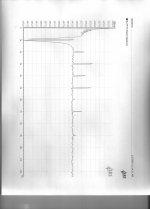
This is the 1KHz distortion residual measured today with my SR-1 analyzer. How can I get even lower, without new test equipment? Anybody?
I take it this is the analyzer looped to the internal signal generator. First question is how does it vary with level? I suspect it is best at somewhere near maximum output. So an external attenuator may be needed to get desired test levels.
Now if this is the test signal used, if you do amplitude and phase FFTs then a baseline to output comparison will give you some insight even if not absolute numbers.
Next step is to build tuned twin T filters for each harmonic and test for one harmonic at a time.
- Status
- Not open for further replies.
- Home
- Member Areas
- The Lounge
- John Curl's Blowtorch preamplifier part III