I'm hopping someone here will be able to assist me in setting up some speakers for a warehouse area.
There are existing speakers and amplifiers but during renovations, everything was unplugged and all wires on the walls were ripped out!!!
I pretty much have to rebuild the previous setup without knowing how it was actually set up. I'm not looking to replicate the previous one. just re-do it right regardless of how it was.
I have:
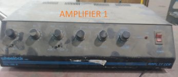
2 x amplifiers
5 x speakers. Each are 8 Ωhm.
Lots of 12 gauge wire
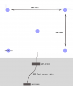
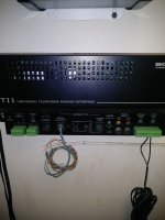
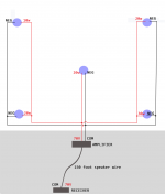
Pictures of layout and all equipment are attached
I was wondering what the proper way to set up the wires in parallel/series would be. (a line drawing would be nice)
Also at which speaker output on the amp should i connect the wires?
Any help would be appreciated.
Thank you for your time.
There are existing speakers and amplifiers but during renovations, everything was unplugged and all wires on the walls were ripped out!!!
I pretty much have to rebuild the previous setup without knowing how it was actually set up. I'm not looking to replicate the previous one. just re-do it right regardless of how it was.
I have:
2 x amplifiers
5 x speakers. Each are 8 Ωhm.
Lots of 12 gauge wire
Pictures of layout and all equipment are attached
I was wondering what the proper way to set up the wires in parallel/series would be. (a line drawing would be nice)
Also at which speaker output on the amp should i connect the wires?
Any help would be appreciated.
Thank you for your time.
Attachments
No big deal with amplifiers, so we leave that for last, some data lacking on speakers.
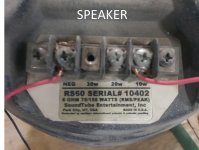
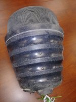
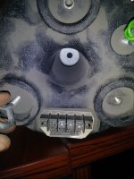
To begin with, and even if visibly labelled so, those are not "8 ohm" speakers any more, since they get power through line transformers.
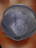
So we need more data on these: a couple more pictures showing them clearly, any other label they have, etc.
Please show clearly the primary connections of those transformers, and any indication whether they are 70V line or 25V line, power amps can drive both.
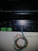
So far you have only shown the secondary connections.
To begin with, and even if visibly labelled so, those are not "8 ohm" speakers any more, since they get power through line transformers.
So we need more data on these: a couple more pictures showing them clearly, any other label they have, etc.
Please show clearly the primary connections of those transformers, and any indication whether they are 70V line or 25V line, power amps can drive both.
So far you have only shown the secondary connections.
I'm pretty sure there's nothing else on the speaker but i'll take more pictures and post them when i'm back at the W/h later on.
As for primary and secondary, i'm not sure what you mean exactly.
Are you referring to the device that I'll attach to the amp.
As for primary and secondary, i'm not sure what you mean exactly.
Are you referring to the device that I'll attach to the amp.
Fat wires have to be run for 8 ohm speakers long distances, so it is much cheaper in large areas to run a 70v system. Your amp has a 70 v output. You can run 18 ga zip cord for that system. Each speaker then should have a 70v transformer. If your speakers are missing the transformer, you can buy them separately in the us from parts-express.com
The transformers are rated by wattage. You use the bigger wattage ones for bigger areas. The secondary of the transformer goes to the 8 ohm speaker, the primary of the transformer goes to the 70 v line of the amp. Several speakers can go in parallel. Do not exceed the sum of the load transformer wattage to the wattage rating of the amp.
The transformers are rated by wattage. You use the bigger wattage ones for bigger areas. The secondary of the transformer goes to the 8 ohm speaker, the primary of the transformer goes to the 70 v line of the amp. Several speakers can go in parallel. Do not exceed the sum of the load transformer wattage to the wattage rating of the amp.
hey Sound Tube "beehives" the rs 60 definitely a 70v line speaker (it's a three way omni design) with built in line matching transformers.
https://soundtube.mseaudio.com/wp-content/uploads/sites/9/RS60.pdf
if there was two amplifiers they may have separated the speaker loads to form two paging zones!?
https://soundtube.mseaudio.com/wp-content/uploads/sites/9/RS60.pdf
if there was two amplifiers they may have separated the speaker loads to form two paging zones!?
Last edited:
Well spotted with regard to the RS60 70V line speakers turk 182!
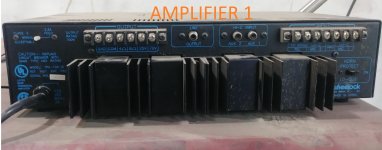
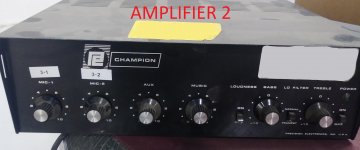
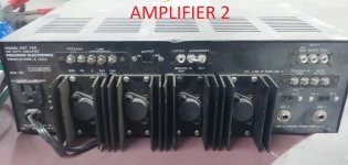
I'd be inclined to use just one of the amplifiers - amplifier 2 looks the more likely candidate.
https://cdn-docs.av-iq.com/dataSheet//60watts%20mixer%20amplifier.PDF
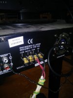
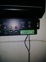
The amplifier is rated at 100W rms. The five speakers can be daisy chained (connected in parallel) with the 'C' for common and the '70V' output terminals of the amp. The output switch should be set to 'line'. The wires may be connected to the 'NEG' and the '20W' terminals on the loudspeakers as 5 x 20W = 100W.
I'd be inclined to use just one of the amplifiers - amplifier 2 looks the more likely candidate.
https://cdn-docs.av-iq.com/dataSheet//60watts%20mixer%20amplifier.PDF
The amplifier is rated at 100W rms. The five speakers can be daisy chained (connected in parallel) with the 'C' for common and the '70V' output terminals of the amp. The output switch should be set to 'line'. The wires may be connected to the 'NEG' and the '20W' terminals on the loudspeakers as 5 x 20W = 100W.
Last edited:
The wattage tappings on the speaker certainly indicate it is purposed for line operation, but we need to be sure that the line transformer on the speaker is set to 70V and not 25V.
So I agree that more photographs of the speakers, particularly of their various connections or switch settings, would be helpful.
So I agree that more photographs of the speakers, particularly of their various connections or switch settings, would be helpful.
Someone hanged the speaker back on the ceiling.
My scissor lift should be charged by tomorrow to go pull it back down and take more pictures.
Turk182, you might be right about the original setup having two paging zones.
the warehouse was split in two. After we took over 3 months ago we removed the division wall and turned it into one large area.
We only really need one paging zone.
Thank you everyone for the help so far.
Ok, after bringing down a speaker and looking at it,
There is nothing else on it other than the ports shown in the original picture.
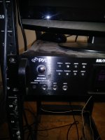
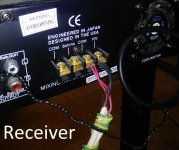
After looking at the receiver they seem to had it plugged in, i noticed they were using the the 70v and COM ports. There is also the paging system that was left behind.
Note: i'm not 100% they had it that way. The wires were ripped all over the place when i received it. I assume their setup was
Phone system->paging system->receiver->amp1 & amp2->speakers
If you look at the wires on picture "receiver 1" you will notice that 2 wires are connected to the 70v and COM ports.
This leads me to believe that they only had 1 zone but because they were separate sections to the warehouse they used two amps to power it. (along with the fact that the paging system is single zone only)
I'll be connecting an Avaya IP500 phone system either using the page trunk port or the audio out jack behind the control unit to the paging system. I would like to set the paging system to also play music when the page is not on but my main concern is simply to get the paging and speakers up and all else is gravy.
I've attached pictures of the receiver and the paging system that was left behind.
Thanks again to everyone for the help.
There is nothing else on it other than the ports shown in the original picture.
After looking at the receiver they seem to had it plugged in, i noticed they were using the the 70v and COM ports. There is also the paging system that was left behind.
Note: i'm not 100% they had it that way. The wires were ripped all over the place when i received it. I assume their setup was
Phone system->paging system->receiver->amp1 & amp2->speakers
If you look at the wires on picture "receiver 1" you will notice that 2 wires are connected to the 70v and COM ports.
This leads me to believe that they only had 1 zone but because they were separate sections to the warehouse they used two amps to power it. (along with the fact that the paging system is single zone only)
I'll be connecting an Avaya IP500 phone system either using the page trunk port or the audio out jack behind the control unit to the paging system. I would like to set the paging system to also play music when the page is not on but my main concern is simply to get the paging and speakers up and all else is gravy.
I've attached pictures of the receiver and the paging system that was left behind.
Thanks again to everyone for the help.
Attachments
Last edited:
Ok, write/phone/beg/ask them for the installation guide for your specific model speaker.
They mention it in the brochure kindly uploaded by turk182:
I have browsed all available at their site and all current ones have a rotary selector labelled 25V -70V and many other clickable settings ... yours does not.
As I see it:
1) they DO have line to 8 ohm transformers.
2) it is inside that plastic beehive shaped baffle
3) usual line transformers have a 25 or 70 or 100 V primary, which should be connected "permanently" to the correct amplifier output line, and various secondaries, not rated in *ohms* but in *watts* , you select taps depending on power needed at that point.
This is the normal way.
4) *educated guess* :
I think they do it the other way; to complicate things they obscure the proper way to do it, show NO wiring data whatsoever on the brochure. WTF?
I am quite certain they do offer the full data (wiring/impedance/power/etc.) to "Authorized Instalers" , maybe as a way to keep captive customers.
They definitely complicate life to people "outside their circle of Trust" such as you or us.
That said, I *guess* they work this way:
* the transformer secondary is fixed and wired to 8 ohm voice coil.
Not visible externally because in any case it´s *fixed* and you can do nothing about that (other than tear baffle open, junk original weird transformer and install a regular one)
* transformer primary is multi tapped, those taps allow you select different power levels.
* you can connect selected primary tap to a regular 70V line.
* which is semi confirmed because the amp has wire pigtails still connected to 70V out winding.
So in a nutshell:
* connect 70V secondary from amp you´ll use to a cable pair running all of the warehouse.
You might use 2 or 3 separate runs to different sites if you find it proper.
* connect each speaker to nearest pair using "Neg" and the desired power terminal: 10/20/30W which defines how much power does that particular speaker "pull" from 70V line.
Total must not exceed 100W , rated amplifier output.
Mix and match as needed; you might have, say, a speaker placed in a noisier area drawing 30W while others down to 10W in quiet ones, or plain set all 5 to "20W" ... yopur choice.
I woukd anyway ask for the proper installation guide, tell them painters/whatever ripped wiring off and didn´t write wiring plan down, ask for specific instructions ... and post them here 🙂
That Company is keeping basic data obscure, and that´s not good.
They mention it in the brochure kindly uploaded by turk182:
A complete installation guide is available from SoundTube Entertainment.
I have browsed all available at their site and all current ones have a rotary selector labelled 25V -70V and many other clickable settings ... yours does not.
As I see it:
1) they DO have line to 8 ohm transformers.
Transformer T-15 T 30
2) it is inside that plastic beehive shaped baffle
3) usual line transformers have a 25 or 70 or 100 V primary, which should be connected "permanently" to the correct amplifier output line, and various secondaries, not rated in *ohms* but in *watts* , you select taps depending on power needed at that point.
This is the normal way.
4) *educated guess* :
I think they do it the other way; to complicate things they obscure the proper way to do it, show NO wiring data whatsoever on the brochure. WTF?
I am quite certain they do offer the full data (wiring/impedance/power/etc.) to "Authorized Instalers" , maybe as a way to keep captive customers.
They definitely complicate life to people "outside their circle of Trust" such as you or us.
That said, I *guess* they work this way:
* the transformer secondary is fixed and wired to 8 ohm voice coil.
Not visible externally because in any case it´s *fixed* and you can do nothing about that (other than tear baffle open, junk original weird transformer and install a regular one)
* transformer primary is multi tapped, those taps allow you select different power levels.
* you can connect selected primary tap to a regular 70V line.
* which is semi confirmed because the amp has wire pigtails still connected to 70V out winding.
So in a nutshell:
* connect 70V secondary from amp you´ll use to a cable pair running all of the warehouse.
You might use 2 or 3 separate runs to different sites if you find it proper.
* connect each speaker to nearest pair using "Neg" and the desired power terminal: 10/20/30W which defines how much power does that particular speaker "pull" from 70V line.
Total must not exceed 100W , rated amplifier output.
Mix and match as needed; you might have, say, a speaker placed in a noisier area drawing 30W while others down to 10W in quiet ones, or plain set all 5 to "20W" ... yopur choice.
I woukd anyway ask for the proper installation guide, tell them painters/whatever ripped wiring off and didn´t write wiring plan down, ask for specific instructions ... and post them here 🙂
That Company is keeping basic data obscure, and that´s not good.
I sent them an email explaining the situation along with a picture of the model&serial
Soundtube reply was
A professional PA installer is supposed to come and take a look at it next week but i've been stood up before and not sure what to expect.
Even so i would like to be prepared if i have to DIY it completely.
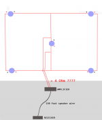
I made a parallel drawing but my issue it that it results to 1.6 Ohms.
I also made another one in series/parallel (which i believe is accurate) that results to 4 Ohms.
Can someone tell me if the series/parallel layout would even work and if it does, is the impedance 4 Ohms or are my calculations off?
Soundtube reply was
We do not have the schematic any longer for this speaker. To wire it, you just need to put your negative wire in the "NEG" terminal and then the positive wire goes in either the 30w, 20w, or 10w terminals, depending on how many watts you are putting into the speaker.
A professional PA installer is supposed to come and take a look at it next week but i've been stood up before and not sure what to expect.
Even so i would like to be prepared if i have to DIY it completely.
I made a parallel drawing but my issue it that it results to 1.6 Ohms.
I also made another one in series/parallel (which i believe is accurate) that results to 4 Ohms.
Can someone tell me if the series/parallel layout would even work and if it does, is the impedance 4 Ohms or are my calculations off?
Attachments
You wire the speakers in parallel and make the connections as described in my post #6 (which assumes the speakers are set up for 70V line operation, as now seems the case).
Disregard your 1.6 ohm idea as this is not how things work in a 70V line system where the speakers are powered by transformers.
Disregard your 1.6 ohm idea as this is not how things work in a 70V line system where the speakers are powered by transformers.
Your internal speaker is 8 ohm (each) but your amplifier does not "see" that at all.
Your amplifier has a 70V 100W output, in this case forget "ohms" because it´s not the useful parameter.
By the same token, each cabinet is not "8 ohm" any more, you are NOT connecting straight to its voice coil but to a line transformer which changes impedance.
In fact, it RISES it a lot significantly.
Just for your information, each speaker shows:
@ 10W: 490 ohm
@ 20W: 245 ohm
@ 30W: 163 ohm
as you see, VERY high impedance, so installation wiring resistance does not hurt at all.
Not sure it´s clear, but: there is NO series/parallel (or plain series) connection in 70V line systems, ALL go in parallel , each speaker using the proper line transformer.
Not sure it´s clear, but: there is NO series/parallel (or plain series) connection in 70V line systems, ALL go in parallel , each speaker using the proper line transformer.
Thank you for that, while it should have been clear to me that since the speakers don't have a transformer, they would require a voltage line, i just never made the connection because i was soo obsessed to figure out what the proper ohm impedance should be.
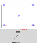
So this simplifies things. I made another diagram which should display the final line connection setup. Is that accurate? Also which is the best input to connect the receiver to the amp?
Thank you everyone so much for all the help provided.
It has really be helpful and instructional 🙂
Attachments

since the speakers don't have a transformer
What i meant to say is that they don't have native power going to their transformer and not that they don't have one.
Just can't seem to edit my previous post so i wanted to make that clear to avoid confusion.
The 70V line output of the receiver is intended to drive 70V line speakers directly. That is, the receiver is an amplifier in its own right.
The 70V line output of the receiver should NOT be connected to the input of amplifier 1 (or 2) as you suggest - damage would result!
Please supply more details/photos of the receiver.
The 70V line output of the receiver should NOT be connected to the input of amplifier 1 (or 2) as you suggest - damage would result!
Please supply more details/photos of the receiver.
Good point about not supplying the amp with add'l voltage 😱
PyleHome PT720A 1000 Watts AM/FM Tuner Hybrid Amplifier W/ 70V Output (manufacturer link)
Could i skip the amp and use the receiver directly?
Manual Attached bellow.
PyleHome PT720A 1000 Watts AM/FM Tuner Hybrid Amplifier W/ 70V Output (manufacturer link)
Could i skip the amp and use the receiver directly?
Manual Attached bellow.
Attachments
Last edited:
You certainly could (and should!). I assume the two microphone inputs on the receiver are adequate for your needs?Could i skip the amp and use the receiver directly?
Last edited:
I assume the two microphone inputs on the receiver are adequate for your needs?
One is all I need to connect the page system but there's an Aux Rca input behind the device. Won't that work?
Also, The distance between the receiver and the speakers will be 200 to the closest and 400-500 to the furthest. Will the signal be strong enough to reach them and adequately broadcast loud enough?
- Status
- Not open for further replies.
- Home
- Live Sound
- PA Systems
- Need help setting up amp and speakers for PA in w/h