This is the output and you can see the wiring scheme. What would be the best way to connect this directly to Soekris board i2s input?
Wow this is such a good question.
hi i just wondering if somebody could give me a leg up on how to access the filter selection using windows serial port is ready to go, just not sure where to begin?
hi i just wondering if somebody could give me a leg up on how to access the filter selection using windows serial port is ready to go, just not sure where to begin?
Check manual. In umanager: set filter = linear/mixed/minimal/soft?
Wow this is such a good question.
The scheme is only for RJ45. Check manual for I2S input requirements and check hifidurino if you need more help.
Here’s the link to the old discussion on synchronized operation in dam1021 again for the record: Reference DAC Module - Discrete R-2R Sign Magnitude 24 bit 384 Khz
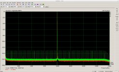
Here a measurement of the jitter test signal of Arta.
Green is a analog loopback of the analyzer in/out. This can be considered as no jitter reference as the ADC and DAC of the analyzer are clocked by the same clock.
Red is the DAM getting its signal from the analyzer via SPDIF.
You see there is next to no difference.

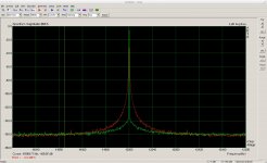
You need an extreme zoom to see deviations

Moreover this is the "differential jitter" between the DAM and the analyzer clock. So the "culpid" of the jitter could analyzer clock if the DAM is more stable.
Green is a analog loopback of the analyzer in/out. This can be considered as no jitter reference as the ADC and DAC of the analyzer are clocked by the same clock.
Red is the DAM getting its signal from the analyzer via SPDIF.
You see there is next to no difference.

You need an extreme zoom to see deviations

Moreover this is the "differential jitter" between the DAM and the analyzer clock. So the "culpid" of the jitter could analyzer clock if the DAM is more stable.
Last edited:
Here a measurement of the jitter test signal of Arta.
Green is a analog loopback of the analyzer in/out. This can be considered as no jitter reference as the ADC and DAC of the analyzer are clocked by the same clock.
Red is the DAM getting its signal from the analyzer via SPDIF.
You see there is next to no difference.
View attachment 733654
You need an extreme zoom to see deviations
View attachment 733655
Moreover this is the "differential jitter" between the DAM and the analyzer clock. So the "cupid" of the jitter could analyzer clock if the DAM is more stable.
zfe thanks for the measurements! Adds a lot to the discussion and to our knowledge of the system performance. It’s probably inaudible, but to get perfect measurement results one would need 1121 or 1941 I guess...
Sorry and last question and to the point what terminal program would the forum suggest to access umanager?
Sorry and last question and to the point what terminal program would the forum suggest to access umanager?
Release Tera Term 4.101 - Tera Term - OSDN
Best choice
I think the noise of the Vref supply is the minor problem, the main issue is the load regulation which trends to be worse. And the load of the DAM is highly nonlinear if I made no error in my old post here:
.....
The correct current draw/output voltage graph is (now hopefully ) this:
View attachment 509360
The main observation that the current is locally more correlated to the number of bits set, remains valid.
Just to avoid misunderstandings, the nonlinearity of the load is not an property of the VRef supply, but of the R2R network (when used like it is in the DAM).
Aha - tnx.
So depending what signal level the DAC is outputting, the resistance of the ladder varies?
//
So depending what signal level the DAC is outputting, the resistance of the ladder varies?
//
Aha - tnx.
So depending what signal level the DAC is outputting, the resistance of the ladder varies?
//
That's it.
The plot is the resistance of the ladder (for the VRef supply) as function of the output level.
Resistance of ladder as seen by the vRef supply - ok!
Did you also check the output impedance linearity of the ladder - can't recall?
//
Did you also check the output impedance linearity of the ladder - can't recall?
//
The plot, as well as the output statement, are computed values of the resistor network, not measurements.
The output resistance assumes a 0 Ohm impedance of the VRef source. But the real value of the impedance of VRef is neglectable for the output resistance, it has some influence on the THD.
I did also a few measurements. They were conform with the computed values.
The output resistance assumes a 0 Ohm impedance of the VRef source. But the real value of the impedance of VRef is neglectable for the output resistance, it has some influence on the THD.
I did also a few measurements. They were conform with the computed values.
- Home
- Vendor's Bazaar
- Reference DAC Module - Discrete R-2R Sign Magnitude 24 bit 384 KHz