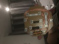
Looks like there are a few incorrectly positioned wires and a missing connection from top end of 2R7 resistor to ground (-ve).
Compare your wiring more carefully against the circuit diagram, make the necessary changes and post a new photo for us to check.
In particular, check the wiring to the W and T output terminal blocks.
P.S. I would advise not to test the crossover until the wiring is verified for fear of damaging your amplifier!
Thank you for the replay I am correct saying putting the earth to the output - connection. And I really can’t see where I have missed a connection on the 2r7 resistor. Or is it me being blind. Once again thank you
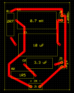
Connect a wire from the top of the 2R7 resistor on your board to the bottom terminal of the input block at the left hand side of the board.
The two wires going to the T output terminal block should be swapped round.
The purple wire from the 0.7mH inductor should go to the top terminal of the UW block, not the bottom one (i.e. join it to the other purple wire coming from the 10uF capacitor).
Re-wire then re-photograph so I can check again.
Thank you so much galu. I will do that now.Connect a wire from the top of the 2R7 resistor on your board to the bottom terminal of the input block at the left hand side of the board.
The two wires going to the T output terminal block should be swapped round.
The purple wire from the 0.7mH inductor should go to the top terminal of the UW block, not the bottom one (i.e. join it to the other purple wire coming from the 10uF capacitor).
Re-wire then re-photograph so I can check again.
P.S. Apologies if the purple wire from the inductor is already going to the top terminal. I couldn't quite tell from the photograph, but now I think it is!
P.S. Apologies if the purple wire from the inductor is already going to the top terminal. I couldn't quite tell from the photograph, but now I think it is!
Well here goes. Please excuse the photos as my phone is on it’s way out. Once again thank you
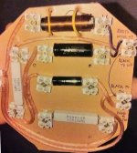
The wiring in your new photo (post # 46) now appears correct.
(No need now to do as chrsng suggests, as his suggestion is based on your old photo and the grounding of 2R7 has already been taken care of in your new photo.)
Make sure that the connections to the input, upper woofer and tweeter are now made with the correct polarity (i.e. + to + and - to -). You can check these connections by looking at your other loudspeaker if necessary - the wires are probably colour coded to help you get them the right way round.
Please let us know how it goes.
welll thank you so much galu I will fitting in toda. Without everyone’s help. I would off not succeed many thank allThe wiring in your new photo (post # 46) now appears correct.
(No need now to do as chrsng suggests, as his suggestion is based on your old photo and the grounding of 2R7 has already been taken care of in your new photo.)
Make sure that the connections to the input, upper woofer and tweeter are now made with the correct polarity (i.e. + to + and - to -). You can check these connections by looking at your other loudspeaker if necessary - the wires are probably colour coded to help you get them the right way round.
Please let us know how it goes.
Can somebody please mow my lawn?
Snigger.
R
Maybe, but only if you pay in beer or wine, and you get rid of the snow first... 😀
Youngie, looks like you've just succeeded in some trouble shooting? Does it sound good?
Maybe, but only if you pay in beer or wine, and you get rid of the snow first... 😀
Youngie, looks like you've just succeeded in some trouble shooting? Does it sound good?
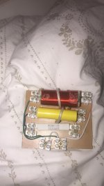
I have just notice my second circuit board is not looking to good so I am thinking I should do that why I am in the speakers. Can anyone help with this part. I have tried and could someone look it over for me many thanks lee
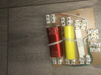
... What's input (from amp) and what's output (to speaker drivers)?
The resistor does not seem to be connected to anything at all on one end?
Is the Orange colored wire connected to anything, or is it just a bridge between the cap and coil?
I can not see properly if all the "sugarcubes" have wires going out of them, (seems like they are unconnected) but are you certain you have followed the schematic properly?
Easiest thing to do might be just glueing a printed schematic onto a board, and put the components and wires exactly like they are on the paper.
Here is my second board replace
Here is the second board hope I have fitted correctly. If not can someone point out where I have gone wrong many thanks
Here is the second board hope I have fitted correctly. If not can someone point out where I have gone wrong many thanks
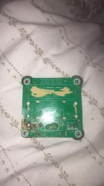
Post a clean shot of the original boards with its measures (width and height) but this time keep the camera directly above the board, not angled like in post #7 so I can trace other parts measures and I will try to draw you the copper traces similar to original so it will look better. Got the soldering iron?
It's really time for you to fly solo Lee!
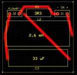
As you were instructed to do with the first board, lay out the components as they are shown in the lower woofer crossover schematic.
Your present layout does not follow a logical pattern so is difficult to follow.
Have another go.
P.S. You have not yet confirmed that the first board worked!
As you were instructed to do with the first board, lay out the components as they are shown in the lower woofer crossover schematic.
Your present layout does not follow a logical pattern so is difficult to follow.
Have another go.
P.S. You have not yet confirmed that the first board worked!
Attachments
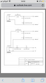
Post a clean shot of the original boards with its measures (width and height) but this time keep the camera directly above the board, not angled like in post #7 so I can trace other parts measures and I will try to draw you the copper traces similar to original so it will look better. Got the soldering iron?
Hi it 3” by 3” many thanks
Attachments
- Status
- Not open for further replies.
- Home
- Loudspeakers
- Multi-Way
- Can some one please draw a me a xover