The design files were updated on January 28, 2019 - please use V1.3 files from post #103
The time has come to publish something really DIY-friendly 😉
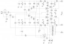
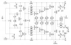
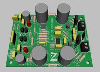
Please welcome Referenz - a relatively simple low-cost amplifier, utilizing current-mode amplification.
Low distortion, low noise. Power rating: 100W @ 8 ohm / 200W @ 4 ohm.
The amplifier consists of IPS module and OPS module.
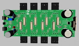
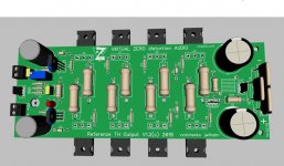
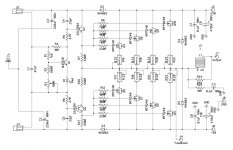
Two OPS variants are included, however, the layout for quasi variant is still under development.
OPS employs commonly-available inexpensive HexFETs.
The amplifier is live-tested - please see the test results in the post #97.
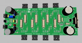
Jeff has designed cool single-sided layouts, slightly tuned-up based on the tests of my prototype.
Questions are welcome - the builds will be supported.
Cheers,
Valery
The time has come to publish something really DIY-friendly 😉
Please welcome Referenz - a relatively simple low-cost amplifier, utilizing current-mode amplification.
Low distortion, low noise. Power rating: 100W @ 8 ohm / 200W @ 4 ohm.
The amplifier consists of IPS module and OPS module.
Two OPS variants are included, however, the layout for quasi variant is still under development.
OPS employs commonly-available inexpensive HexFETs.
The amplifier is live-tested - please see the test results in the post #97.
Jeff has designed cool single-sided layouts, slightly tuned-up based on the tests of my prototype.
Questions are welcome - the builds will be supported.
Cheers,
Valery
Attachments
-
 01 Referenz Input @Sch 1.2.jpg166.8 KB · Views: 2,050
 -
Referenz Files.zip357.5 KB · Views: 213
-
 @Referenz Loop Analysis.jpg132.4 KB · Views: 590
 -
 03 Referenz Output Quazi.JPG96.7 KB · Views: 603
 -
 02 Referenz Output.JPG98.5 KB · Views: 1,789
 -
 01 Referenz Input.JPG66.6 KB · Views: 1,897
 -
 03 Referenz Output Quazi @Sch 1.2.jpg210.4 KB · Views: 1,977
 -
 02 Referenz Output @Sch 1.2.jpg209.9 KB · Views: 2,066
Last edited:
HI Valery,
Happy new Year to you. Take a look a skype Please.
Marc
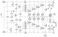
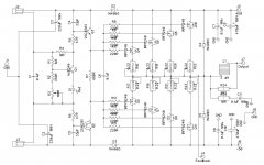
Hi Marc, happy New Year! Thank you for observation - on both OPS schematics Q10 must be IRFP240 - the symbol is right (n-channel), but the marking is strangely mistaken. I will reload the corrected diagrams soon.
Valery, have you changed the scale of your diagrams?
Suddenly they are much more readable 🙂
Suddenly they are much more readable 🙂
The time has come to publish something really DIY-friendly 😉
I never noticed the typo in the schematics either. Thanks Marc.
I changed the line display thickness in Diptrace to make the printed schematics more legible. I think these settings remain when Valery prints from them.
I changed the line display thickness in Diptrace to make the printed schematics more legible. I think these settings remain when Valery prints from them.
Yes, those thicker lines make the diagrams looking much better.
PDF files in the zip archive make them even more convenient as they scale easily.
PDF files in the zip archive make them even more convenient as they scale easily.
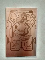
I can't call this home etching friendly,especially the hole pads. 🙂
Emmm... we actually tried to use "fatter" pads, but some of them still appear to be rather thin 🙄 Something to improve in the next version


The time has come to publish something really DIY-friendly 😉
Please welcome Referenz - a relatively simple low-cost amplifier, utilizing current-mode amplification.
Low distortion, low noise. Power rating: 100W @ 8 ohm / 200W @ 4 ohm.
The amplifier consists of IPS module and OPS module.
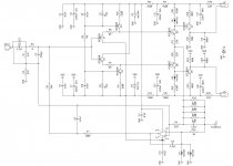
Two OPS variants are included - complementary and quasi-complementary.
Both variants employ commonly-available inexpensive HexFETs.
It's not live-tested yet, so early adopters may face some amendments.
At the same time, some solutions used in this design are rather mature, being used earlier in the other designs.
Jeff has designed cool single-sided layouts.
Questions are welcome - the builds will be supported.
Cheers,
Valery
looks good , like my first CFA.
One comment , you chose to servo the low Z FB.
Have you tried either servo(ing) the CCS's or the high Z input.
Thimios did all 3. The high Z worked , 1M ohm Z load for the op-amp.
Servo FB to the CCS's also worked , but added more components.
PS- with especially an extreme input pair mismatch , the servo does
not have the "horsepower" to compensate the current FB node.
Servo FB is the "anal" way , since FB is independent of the audio paths.
OS
Hi Pete!
Glad to see you here!
Driled, not my best but still usable, i hope.
If changes, i hope some flying parts will do the job. 😕
This time nothing works first time. 🙁
I haven't any photoresist remaining and the transperance not function well. 🙁
Glad to see you here!
Driled, not my best but still usable, i hope.
If changes, i hope some flying parts will do the job. 😕
This time nothing works first time. 🙁
I haven't any photoresist remaining and the transperance not function well. 🙁
Attachments

looks good , like my first CFA.
One comment , you chose to servo the low Z FB.
Have you tried either servo(ing) the CCS's or the high Z input.
Thimios did all 3. The high Z worked , 1M ohm Z load for the op-amp.
Servo FB to the CCS's also worked , but added more components.
PS- with especially an extreme input pair mismatch , the servo does
not have the "horsepower" to compensate the current FB node.
Servo FB is the "anal" way , since FB is independent of the audio paths.
OS
Hi Pete,
Thank you for the observation - the servo connection is actuallu a mistake 🙂
It happened when redrawing the schematic in Diptrace.
Jeff - we've got a problem 😛
56K resistor has to be connected not to the low Z FB node, but to the high Z input (input pair's bases). This is an inverting servo, so it is intended for controlling the input, opposite the one with the feedback.
Thimios - sorry, you will need to cut the trace and reconnect the 56K resistor's lead.
Pete - I thought about driving the CCSs with the servo, but this design had a special requirement, driving my choices - it had to be as low-cost and low part count as possible (still showing very good sound quality characteristics).
Driving the high Z input with servo is a proven solution I used in the past. 56K resistor's value is chosen for having the overall input Z at the level of 27K (in parallel with 47K connected to ground).
We will upload the corrected files to the Post #1 soon 😉
Cheers,
Valery
D3 in quasy scheme is not on place.
Emmm... please elaborate 🙂
Looking at the schematics I see it in the same place.
I see the mistake in the servo connection now. That'll be a bit of an ugly jumper wire job to get that connected correctly! Wrong end of the board.
Yes D3 is in place on the Quasi board. Top left.
Yes D3 is in place on the Quasi board. Top left.
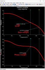
UPDATED FILES
Here are the corrected files with all amendments implemented and etching-friendly pads on all the boards.
I will update post #1 as well, however, the system doesn't allow me updating the files there (only allowing updating the text).
Here are the corrected files with all amendments implemented and etching-friendly pads on all the boards.
I will update post #1 as well, however, the system doesn't allow me updating the files there (only allowing updating the text).
Attachments
-
 @Referenz Loop Analysis.jpg132.4 KB · Views: 231
 -
 03 Referenz Output Quazi.JPG96.7 KB · Views: 207
 -
 02 Referenz Output.JPG441.8 KB · Views: 222
 -
 01 Referenz Input.JPG66.6 KB · Views: 338
 -
 03 Referenz Output Quazi Sch 1.2.jpg154.8 KB · Views: 725
 -
 02 Referenz Output Sch 1.2.jpg149.4 KB · Views: 736
 -
 01 Referenz Input Sch 1.2.jpg129.8 KB · Views: 742
 -
Referenz Files 01 Corrected PDF.zip349.7 KB · Views: 173
- Status
- Not open for further replies.
- Home
- Amplifiers
- Solid State
- Referenz - high-quality low-cost diy-friendly amplifier