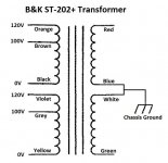
I think I figured it out. Before I said the 0,1,3 & 4,8,7 were the secondaries, however after looking closely at the pictures they're actually the primaries. The brown wire should pair with the gray wire on the center terminal of the 3 terminal connector.
#0 & 4 are paired (black & yellow) 0V primary tap
#1 & 8 should pair (brown & grey) 100V primary tap
#3 & 7 are paired (orange & violet) 120V primary tap
It looks to me like the amp is set on the 100V primary taps and not the 120V taps like it should be. This would mean higher DC rail voltages, corresponding to the 87.5V DC you measured the other day. Even though your now measuring in the high 70's for DC volts this is still higher than it should be.
What does your AC voltage from the wall measure? Your Killawatt will show you this voltage.
You could move the black wire going from the switch to the center terminal over one to be on the orange & violet terminal. Before moving it I would install the variac and DBT and measure the DC rail volts at the top of one of the main capacitors and record it. Then power down unplug the AC power and move the center terminal black wire over to the orange and violet terminal. Then plug everything back in and turn the variac up slowly with your meter showing the same DC rail as measured on top of one of the main capacitors. When you get to to top of the variac range the DC volts should be about 20% lower than before. As long as the volts are below the 75vdc rating of the caps then power down and remove the variac and DBT and then power back up. The DC rail volts should come back up a bit with the DBT out of the circuit.
If for some reason the volts are going to end up much higher when you're ramping the variac up after swapping the black wire from the switch then that means that the center terminals (brown & grey) were in actuality the 120V primary taps. So you'll need to power the amp off and move the wire back from the orange & violet terminal to the brown & grey terminal.
I just looked at the picture I found before of the same model 202+ as yours online, I posted it many pages back in this thread. It appears that B&K set the primary tap at 100V on all of these amps. I say this because that amp is set the same way as yours with the brown & grey wire pair being used for the incoming power.
I assume that they wanted higher voltage for this model and this is why they are using the 100V taps.
So don't move the black wire as I suggested. Just reconnect the brown wire to be paired with the grey wire. I would connect the DBT for the first time you power it up after reconnecting the brown wire just to be safe.
As long as your DC RAIL voltage is close to 75V +/- a few volts you should be where B&K intended the amp to be.
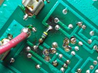
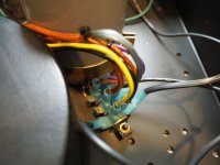
They're not both orange wires. One of the wires is brown and the other is orange, they've faded with age. The picture of the ST202+ that Phase linked to confirms this.
According to your picture of the voltage rating plate it appears that the secondaries are probably wires #0,1,3 & #4,8,7. The center number in each series I would imagine should be the center tap. Maybe someone more savvy than me with transformers can take a look at the plate and figure out which wires should be the primary/secondary. If that doesn't happen your only recourse may be to find another ST-202 owner to send you a picture or two.
My bro in law has the same amp. Hopefully it's the same inside. I'll ask him to do this weekend. Oh, the "orange" wire that maybe is brown, has shrunk sticky insulation on it. Strange. This insulation is cloth-like, but it's the only wire like this. All other wires seem to be normal, in that the outer jacket is dry and not sticky. I'm guessing that could be from heat over many years?
Myself before I begin touching anything inside of a piece of gear that I am unfamiliar with I take multiple pictures of the interior from various angles, wire routing, orientation of capacitors & components, connections, etc. If you do that in the future you'll minimize the chances of knocking something loose and not knowing where it attaches or if its unused. Even just poking around or dusting things off could result in a wire pulling loose or breaking at a solder joint and it can be a PITA to figure out where it went.
Also just so you know you cannot rely on the silkscreen on a board, you need pictures of the board before you disassemble it to verify that you've placed components in their proper orientation before soldering the new parts in. I have many times found production gear that has incorrect polarity marking on the board for a random component. The only way you'd know this is by checking the pictures prior to disassembly and comparing those pics to how you're placing the new components. Failure to do this will bite you hard!
Good advice. I normally get all the pictures I need for reference. For whatever reason, I didn't get this one angle on the transformer wires at the voltage terminal.
The tech out here who said one channel had 150wpc, while the other was unplugged ... I just wonder if this wiring had anything to do with that? I'm going to read your later posts ...
Last edited:
I just looked at the picture I found before of the same model 202+ as yours online, I posted it many pages back in this thread. It appears that B&K set the primary tap at 100V on all of these amps. I say this because that amp is set the same way as yours with the brown & grey wire pair being used for the incoming power.
I assume that they wanted higher voltage for this model and this is why they are using the 100V taps.
So don't move the black wire as I suggested. Just reconnect the brown wire to be paired with the grey wire. I would connect the DBT for the first time you power it up after reconnecting the brown wire just to be safe.
As long as your DC RAIL voltage is close to 75V +/- a few volts you should be where B&K intended the amp to be.
Now that I have the amp part-way apart, I'll have to test this after the boards are done and back in place. Are you thinking the loose "orange" wire is actually brown? If so, it was close to the the empty tab connector by the gray wire. I wish they would have used colors closer to what I would think ... the grey insulation looks blueish, but it's not. I'm used to seeing gray as gray ...
My last V measurements were at 77v ... I'm still thinking about bigger caps, but I want to get through the output boards first. I started a list on Post #1 where I'll track the parts on the board that could be replaced. I assume/hope all my transistors are fine. The resistors "look" fine, but the one resistor (shunt?) on the backside of the board that connect the two can style transistors has what I would refer to as dark areas. I'll get pictures posted in the morning. I just got home. Then you'll be able to see what I'm looking at.
Overall, the caps look good, but I'll replace the electrolytics for sure. There are three poly's that I'd like to replace if it makes sense. I'll catch up in the morning. I have to eat some dinner.
Yes, the loose wire is the brown wire, it seems more of a dark tan color in the picture. Looking at the picture the wire which is more orange in color is properly paired with the violet wire on the rear terminal.
On the matter of the amp only putting out 150wpc while at the tech. This would not be due to the brown wire being loose. With the brown wire disconnected the amplifier will not work, at all, so this wire had to have come loose after the last time you played music through the amp.
At 77V on the DC rails just go with an 80V or higher rated capacitor and you'll be fine.
Output Boards - Let's get some parts ordered!
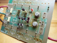
Here are pics of one output board. I'll get the other board out this weekend to see if there are any surprises. But I don't expect.
First is a reference shot of top, minus trim pots (500k). I should note that the bias trimpot only measured 481k at full turn.
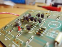
There are three component types I'm wondering if I should change.
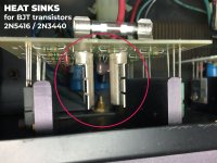
The two yellow poly caps (C6-7) ... the brown poly cap (C8) ... and bipolar BJT transistors that have what looks like an overheated shunt resistor on the trace side. The 2N5416/2N3440 pairs have aluminum heat sinks that are not in these shots.
All the TO92 transistors look good, and based off the amp sounding great, I feel no need to change those. In fact, I'd say aside from electrolytic caps, nothing else "needs" updating, unless there are parts prone to going out. The more I save here, the more I have for ps caps, which I think need to be done, and I'll most likely remove to have more room to resolder boards back in clean and neat.
Here are pics of one output board. I'll get the other board out this weekend to see if there are any surprises. But I don't expect.
First is a reference shot of top, minus trim pots (500k). I should note that the bias trimpot only measured 481k at full turn.
There are three component types I'm wondering if I should change.
The two yellow poly caps (C6-7) ... the brown poly cap (C8) ... and bipolar BJT transistors that have what looks like an overheated shunt resistor on the trace side. The 2N5416/2N3440 pairs have aluminum heat sinks that are not in these shots.
All the TO92 transistors look good, and based off the amp sounding great, I feel no need to change those. In fact, I'd say aside from electrolytic caps, nothing else "needs" updating, unless there are parts prone to going out. The more I save here, the more I have for ps caps, which I think need to be done, and I'll most likely remove to have more room to resolder boards back in clean and neat.
Attachments
-
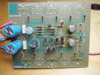 output_reference.jpg243.7 KB · Views: 83
 -
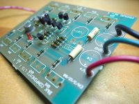 output_yellow-caps_sm.jpg344.1 KB · Views: 62
 -
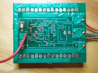 output_trace-full_sm.jpg526.2 KB · Views: 55
 -
 output_heat-spot_sm.jpg533.8 KB · Views: 58
 -
 output_caps-2_sm.jpg348.8 KB · Views: 79
 -
 output_caps_sm.jpg276.9 KB · Views: 80
 -
 output_reference-2_sm.jpg442.6 KB · Views: 78
Last edited:
looking at the photo and the schematic it looks like the brown wire should be connected to the grey wire so that the two primaries are in parallel.
If your mains voltage is close to 120V then move the black (power switch) wire to the tab of the orange/violet Wires. In that case, the brown wire can be left disconnected.
If your mains voltage is close to 120V then move the black (power switch) wire to the tab of the orange/violet Wires. In that case, the brown wire can be left disconnected.
My mains are about 123v right now, measuring with my killawatt meter, both at wall, and surge protector.
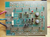
Here's a pic of the heatsinks on the BJT transistors ... these transistor types are pricey, and the amp sounded great before pulling apart, so I'm inclined to believe all transistors are fine. However, after saying that, if you look at the trace side of the board with there is a resistor across the connector legs ... you can see where over a period of time, heat has discolored the board.
Attachments
I put this together using your pictures.
This should be the ST-202+ transformer wiring.
I'm confused.
Looking at this schematic, it appears that my choices are to run at 120v or 100v ... and so keeping the amp as it is now, with orange/violet, it's set for 120v. If I connected brown/grey (100v), wouldn't that be a problem?
Another question ... you can see from the pic here, the insulation jacket on the orange wire has a gap to the connector. Is that a problem, or can I leave it? I don't see how anything could touch it, but I'm guessing it originally fit loose inside the tab insulator. I could get some 3:1 heat shrink to close the gap.
Here's a pic of the heatsinks on the BJT transistors ... these transistor types are pricey, and the amp sounded great before pulling apart, so I'm inclined to believe all transistors are fine. However, after saying that, if you look at the trace side of the board with there is a resistor across the connector legs ... you can see where over a period of time, heat has discolored the board.
The heat that discolored the board came from the transistors not from the resistor. The amp was working fine, leave them be!
Realistically you probably shouldn't be going this deep into this amp. You don't have the necessary test gear to troubleshoot it if you were to create a problem while working on it at this level. It's one thing to change a couple of PS capacitors and something completely different to begin swapping transistors and other components.
You need a 2nd better meter, o-scope, 4/8 ohm dummy loads and a decent signal generator. If you want to test even further then a decent distortion analyzer and/or sound card is in order.
Gotcha. So then my question would be other than the 4 electrolytic caps, should I keep the two yellow poly's and brown poly?
I'm confused.
Looking at this schematic, it appears that my choices are to run at 120v or 100v ... and so keeping the amp as it is now, with orange/violet, it's set for 120v. If I connected brown/grey (100v), wouldn't that be a problem?
Another question ... you can see from the pic here, the insulation jacket on the orange wire has a gap to the connector. Is that a problem, or can I leave it? I don't see how anything could touch it, but I'm guessing it originally fit loose inside the tab insulator. I could get some 3:1 heat shrink to close the gap.
The orange/violet pair has no input AC power to them so they are not being used.
The Brown/grey pair has the AC power (black wire) from the switch, that's the incoming power so that is the active voltage tap. To use the Orange/Violet (120V) pair you'd have to move the black wire from brown/grey to the Orng/Vio pair. However don't do this because B&K set up the amps to run on the 100V transformer tap. I found a picture online that shows another ST-202+ the exact same model as yours and the tap is set for 100V. Changing the tap to 120V will drop your DC rail volts down close to 60V, you will have a 150W amp for sure if you do that...probably less.
When I connected the brown wire, the tab was not tight and it popped off. This makes me think it was originally connected. As it stands, looks like we have the correct connections at the voltage terminal. Thanks guys!!
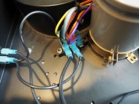
As you can see from the pic below, I have connected both pairs of windings, so that moving the power switch wire to either one is simple. I zip tied each pair to keep it organized.
As you can see from the pic below, I have connected both pairs of windings, so that moving the power switch wire to either one is simple. I zip tied each pair to keep it organized.
Attachments
Recrimp the end of the female spade connector with a pair of pliers, not too much or else it'll never go back on. This will tighten it back up to the way it was when new.
Leave AC power from the switch connected to the 100V winding.
Leave AC power from the switch connected to the 100V winding.
I would get the power sorted out first before rushing into capacitors.
Being in a hurry has never produced a good result for me with electronics and audio.
Being in a hurry has never produced a good result for me with electronics and audio.
Gotcha. So then my question would be other than the 4 electrolytic caps, should I keep the two yellow poly's and brown poly?
The brown one is not a poly it looks like a silver mica.
I would just leave all of the film caps alone. Make sure you're replacing bipolar caps with bipolar caps.
- Status
- Not open for further replies.
- Home
- Amplifiers
- Solid State
- B&K ST-202 Plus :: hum