Overhang voice coil?
Equal length will do it. Symmetrical flux times x/gaplength, falls off on both sides. That'll do third.
Jn
Keantoken. My eddy machine was to initially look for eddy drag gap flux dragging/ reluctance path modulation. I was not considering force, but rather just a gauss meter. I can think of mounting the motor on a rotating base with a spring to measure torque, but that may be difficult with all the bandages on my hands where my fingers used to be. (Thinking of all contingencies should my neo magnets "misbehave" during assembly).😱
Eddy force is directly proportional to velocity.
Jn
Last edited:
John
Get well soon (what's the problem?)
George
Get well soon (what's the problem?)
Ask your doctor if he agrees that Bloody Mary is a clear liquid.Drink plenty of clear liquids
George
Still no way to generate 3rd harmonics magnetically. 🙁
Easy move the voice coil off center. Getting and keeping a voice coil centered is very much non trivial. Even if you can get the voice coil originally positioned to be aligned within 1/2 of the diameter of a voice coil wire diameter it will still move.
In most applications the weight of the cone will cause the suspension to allow some movement. Woofers have thicker wire and more cone weight than smaller transducers. Tweeters have almost no weight but finer wire which makes perfect alignment rather hard.
Then we could talk about limits to manufacturing reproducibility.
JN, Woo hoo I win the big loudspeaker contest! Amazing what it takes to deliver 112 dBA peaks to 80,000 or so folks at a distance averaging around 1,200 inches. (Sounds bigger that way!)
Last edited:
Sigh, ok..humor tanked for a fourth time (or was it five now?)John
Get well soon (what's the problem?)
Ask your doctor if he agrees that Bloody Mary is a clear liquid.
George
It's the old joke.. doc told me to drink clear liquids and eat greens... Ok, so I'll have my martini with olives..
That may even be Dean Martin, maybe George Burns..
Jn
Ed, whenever I think of you, I think Marty McFly in front of that 50 inch speaker..
112 dBa, 80,000 people, 1200 inches..pfft I can do that easily...
Wait, are they supposed to survive?
Ed, happy new year.
Last edited:
As the joke went Dean Martin would eat hay! If you put it in alcohol. (Pretty sure that was from Pat Buttrum (sp?) aka known as Mr. Haney.)
JN-
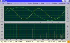
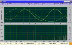
This was a quick test of what you were asking to see if its close. These are first, the current waveform with the fundamental removed (from a 1 Ohm sense resistor) and second, the differential signal per discussion. The sync for the wave is the voltage going into the driver. The feedback is not connected. Not sure about the phase relationships. Too many differential probes to sort out (especially with a martini beckoning). Is this going the right way? (I really like DiAna for its ability to put the nonlinearities in sync with the fundamental, like the Shibasoku 725)
This was a quick test of what you were asking to see if its close. These are first, the current waveform with the fundamental removed (from a 1 Ohm sense resistor) and second, the differential signal per discussion. The sync for the wave is the voltage going into the driver. The feedback is not connected. Not sure about the phase relationships. Too many differential probes to sort out (especially with a martini beckoning). Is this going the right way? (I really like DiAna for its ability to put the nonlinearities in sync with the fundamental, like the Shibasoku 725)
Attachments
Let me state what I got from that so we are on same page.JN-
This was a quick test of what you were asking to see if its close. These are first, the current waveform with the fundamental removed (from a 1 Ohm sense resistor) and second, the differential signal per discussion. The sync for the wave is the voltage going into the driver. The feedback is not connected. Not sure about the phase relationships. Too many differential probes to sort out (especially with a martini beckoning). Is this going the right way? (I really like DiAna for its ability to put the nonlinearities in sync with the fundamental, like the Shibasoku 725)
So first is green current, yellow is distortion residue of current, voltage drive.
Second is green current yellow differential voltage, voltage drive.
With voltage drive, current shows the second harmonic, thinking Le(x) as cause.
Second is what the second coil subtracted from first shows, which is also second harmonic.
If they are phase oriented, it should be possible to use the diff as feedback to kill the current distortion and zero H2.
If current driven, how does the diff signal relate to current drive?.
Nice data, thank you.
Happy new year, here's hoping the new year brings good collaboration and many a sacrificial olive (preferably blue cheese stuffed).
Jn
Current driven will need to wait.
Your understanding is correct. What I can do soon is measure the acoustic distortions using the same setup and add the feedback looking at the variations. I think adding the feedback will remove H2 and all the rest of the harmonics will be easier to see.
And I usually prefer cocktail onions, from a specialist in Oregon. . .
Is it just me or does the 2nd residual look like it is FM modulated by the fundamental? It's squished towards the right half.
Oooooooh, not bad. A Gibson?And I usually prefer cocktail onions, from a specialist in Oregon. . .
Jn
Is it just me or does the 2nd residual look like it is FM modulated by the fundamental? It's squished towards the right half.
If you mean amplitude modulated, it is not just you. It was predicted.
However, it might be better to fully process all data, it may require significant averaging to eliminate false attribution.
Jn
Last edited:
Demian, if you switch to the coherent FFT view, we can see which harmonics are buried in noise so we know which ones to ignore. You can then remove them with the LP filter function to remove potential confounders from the residual. Why is the residual so noisy?
Do you mean 30m ?........JN, Woo hoo I win the big loudspeaker contest! Amazing what it takes to deliver 112 dBA peaks to 80,000 or so folks at a distance averaging around 1,200 inches. (Sounds bigger that way!)
I work on and am surrounded by this stuff.
That and just about every industry standard live dynamic and condenser mic.....that and just about every industry standard classic and modern mix console....and, and....
What really is mind blowing is the logistics and sheer amount of gear of all categories that goes into the likes of an AC/DC or Adele etc stadium show and all for one or two performances usually...it's bezerk !.
Dan.
Does that residual represent noise in the magnetic structure, ie noisy magnetic level ?.Why is the residual so noisy?
Dan.
Last edited:
Its not calibrated but the drive is about 1v and the fundamental amplitude is less than 100.mV. The 2nd harmonic is 40+ dB below that, 1 mV. So you are looking a low level stuff with only.7 or 8 averages.
I wanted to confirm I'm on the right track before doing a lot of testing.
Next round will be more formal.
I wanted to confirm I'm on the right track before doing a lot of testing.
Next round will be more formal.
Is it just me or does the 2nd residual look like it is FM modulated by the fundamental? It's squished towards the right half.
Agree about apparent squishing on the time axis. Could just be an optical illusion though, don't know.
Last edited:
To the selected few who go into the great trouble to test or simulate and post their contribution here.🙂
Is it possible please, along the screen shot results to be shown the test setup schematic and the probe pick-up points, plus a clear label as to what each screen shot and each colored line intend to show?
Words are not always capable to explain what is shown and under what condition.
Ambiguity is to be avoided. It leads to misunderstanding and confusion
George
The instantaneous frequency of a narrow-band signal can be determined by the so-called parametric spectral analysis, i.e. by a simultaneous analysis of the signal in the time and frequency domains.Agree about apparent squishing on the time axis. Could just be an optical illusion though, don't know.
If there is interest I can present an example.
Regards,
Braca
Max,
On reasonably good terms with the D & B Audiotechnik guys. I find it quite impressive as to how well they speak English. They have done custom loudspeakers for a project of mine. Went so far as having one of their Backnag guys stop by to visit. Showed him the small town where my shop is located. It was built by German settlers and follows that architecture style.
On reasonably good terms with the D & B Audiotechnik guys. I find it quite impressive as to how well they speak English. They have done custom loudspeakers for a project of mine. Went so far as having one of their Backnag guys stop by to visit. Showed him the small town where my shop is located. It was built by German settlers and follows that architecture style.
- Status
- Not open for further replies.
- Home
- Member Areas
- The Lounge
- John Curl's Blowtorch preamplifier part III