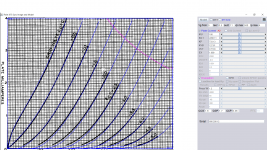
Here it is.very good info thanks so please can you draw a line here according to this schematic? thank you very much
The left triode gives more then 16mA at 0 volts, way out of the picture.
The resistor(s) left gives, with 15k+1k5=16k5, a slope of 1mA every 16V5.Another way to draw the line

I placed a dot on the working point.
Mona
Attachments

Thanks Mona you are a star, now do you think the first triode could be set better that that? I mean can this configuration work well or is better change the cathode load resistors?
Very good text thanks
That's what I am talking about, thank you very much this is exactly what I was looking for, I already read all and is very well explained with right balance of math and examples.....thanks again Rayma
Very good text thanks
Read this carefully. http://ken-gilbert.com/images/pdf/acpart1.pdf
That's what I am talking about, thank you very much this is exactly what I was looking for, I already read all and is very well explained with right balance of math and examples.....thanks again Rayma
Mona's load lines show why this is a difficult example on which to learn. The 12AX7 can be (and often is) abused, and still works well. The "left triode" is working way outside its design purpose, but still stays pretty linear. It's not obvious why the load line is "difficult". For learning purposes, you may want to start with something more pathological. 12AT7 curves are easily available; maybe try drawing those same load lines on a 12AT7 curve set, or a 12AU7. Easy and interesting, at least.
All good fortune,
Chris
All good fortune,
Chris
Last edited:
Bewared of the excessive grid current leak and shorten tube live if load is difficult, if you use another brand other than RCA, it will not sound the same. In guitar amp the current drawn is often > 1mA for a special effect. Beside higher distortion and less gain what wrong with proper load, only to drive a tone pad? Do you know the frequency response and Zout required? Why abuse after-all?
if you had even rudimentary training in electronics, it should be quite easy to follow, or you can ask Merlin to write another book...
That's a splendid idea. Most of these of these old, hard to follow technical books should be rewritten as "millennial editions" 🙂
@Koonw - Hmm... your comment above does not seem to help the OP at all, all he wanted to know was how to draw a load line, given the conditions shown by RCA. Your load line in #18 does not make much sense, perhaps you would like to elaborate or correct?
Yes, OP also asked (Mona) in #22"
To help decide if it makes sense or I have to sim it (don't blame me abuse the simulator), I made brand new RCA 7025 model based on attachment. For OP or anyone interest in the model:
So if 15k is a difficult load, how about a proper load such as post#18? Every body has hard time figure out why used such as a difficult load not even for 12au7. We can use formula to hand compute the minimal load of this cathode follower, I bet 15k is almost any impossible load for 7025 (less noisy version of 12ax7).Thanks Mona you are a star, now do you think the first triode could be set better that that? I mean can this configuration work well or is better change the cathode load resistors?
To help decide if it makes sense or I have to sim it (don't blame me abuse the simulator), I made brand new RCA 7025 model based on attachment. For OP or anyone interest in the model:
Code:
**** 7025_RCA ******************************************
* Created on 12/26/2018 14:21 using paint_kit.jar 3.1
* [URL="http://www.dmitrynizh.com/tubeparams_image.htm"]Model Paint Tools: Trace Tube Parameters over Plate Curves, Interactively[/URL]
* Plate Curves image file: 7025_rca.png
* Data source link:
*----------------------------------------------------------------------------------
.SUBCKT 7025_RCA 1 2 3 ; Plate Grid Cathode
+ PARAMS: CCG=1.6P  CGP=1.7P CCP=0.46P RGI=2000
+ MU=100 KG1=2206.11 KP=733.13 KVB=127.61 VCT=0.7104 EX=1.609
* Vp_MAX=500 Ip_MAX=4 Vg_step=0.5 Vg_start=0 Vg_count=11
* Rp=4000 Vg_ac=55 P_max=1.2 Vg_qui=-48 Vp_qui=300
* X_MIN=43 Y_MIN=9 X_SIZE=951 Y_SIZE=753 FSZ_X=1550 FSZ_Y=878 XYGrid=false
* showLoadLine=n showIp=y isDHT=n isPP=n isAsymPP=n showDissipLimit=y
* showIg1=n gridLevel2=n isInputSnapped=n
* XYProjections=n harmonicPlot=n dissipPlot=n
*----------------------------------------------------------------------------------
E1 7 0 VALUE={V(1,3)/KP*LOG(1+EXP(KP*(1/MU+(VCT+V(2,3))/SQRT(KVB+V(1,3)*V(1,3)))))}
RE1 7 0 1G  ; TO AVOID FLOATING NODES
G1 1 3 VALUE={(PWR(V(7),EX)+PWRS(V(7),EX))/KG1}
RCP 1 3 1G   ; TO AVOID FLOATING NODES
C1 2 3 {CCG} ; CATHODE-GRID
C2 2 1 {CGP} ; GRID=PLATE
C3 1 3 {CCP} ; CATHODE-PLATE
D3 5 3 DX ; POSITIVE GRID CURRENT
R1 2 5 {RGI} ; POSITIVE GRID CURRENT
.MODEL DX D(IS=1N RS=1 CJO=10PF TT=1N)
.ENDS
*$
Attachments
Last edited:
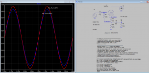
Thanks for the clarification, however, since #18 came before #22, it wasn't clear what you were trying to convey... 🙂 In any case, there were some errors in the figures shown by RCA - the cathode and the grid voltages were off for the left triode, which were verified by your sim.
wowww great job Koonw, now things getting clearer with the help of everyone, so that mean when a new circuit is created we must take in consideration theory and practicality also so the good result is a combination of both element, because I thought the RCA circuit was impossible to work under any circumstances but after the comment of Chris #23 and the V(out) scope projection of Koonw #27 show that some tube like the 12ax7 can work quite well even out of their comfort zone.
With 100% NFB, almost anything would work... 😉
Sorry what is NFB?
It just means that a cathode follower has a gain of < 1, due to internal N(egtive) F(eed)B(ack), the feedback is 100% (max. total) when cathode resistor is not bypassed (by a capacitor or others). This feedback will correct output hence reduce distortion making almost any load would work (jazbo8). I'm not surprised the value of Rk has been selected and tested for best sounding, so you can also do the same.
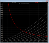
I plotted extended range for 7025 for the convenience of OP and other non spice users so that of 0V of loadline is in full view.
I plotted extended range for 7025 for the convenience of OP and other non spice users so that of 0V of loadline is in full view.
Attachments

That is widely believed to be true. It is completely false!kodabmx said:Also, a low mu triode like 6SN7 and the like will be a much better cathode follower IMHO. Lower Zout, more current.
For a near-perfect cathode follower you need high transconductance and highish mu. It is the high transconductance which gets you low output impedance, and the high mu which stops you from wasting gain. To a first approximation:
CF output Z = 1/transconductance
CF gain = 1 - 1/mu
Interesting. Thanks for the DF96. High transconductance excludes 12AX7 to me. The 6F12P on the other hand... 🙂
The ECC83/12AX7 has quite high transconductance for the amount of current it draws, so could make a good CF in a high impedance circuit. However, in most cases an ECC81/12AT7 or ECC88/6DJ8 would be better as CF; the popular ECC82/12AU7 makes a poor CF: low transconductance, low mu. I guess it is popular as a CF because people wrongly believe that low anode impedance means low CF output impedance.
12AU7 is not "the best" of the 12A_7 series, for most uses, but is often just fine.
You can pick bias and load values directly from the Resistance Coupled Amplifier tables. Just put the parts in the other order. The tube does not know the difference.
12AX7 for loads over 100K. Up here, 12AX7 is thriftiest.
12AT7 R-C Amp Tables do not go as low as the AT7 can drive. 47K is perfectly reasonable.
12AU7 may be marginally better for loads 47K to 25K. Parallel 12AU7 for modern 22K studio inputs.
I'm not overwhelmed by concern of "gain" or "THD" because the decrease of gain or increase of THD is usually dominated by the plate-loaded gain stages ahead of the CF.
- Status
- Not open for further replies.
- Home
- Amplifiers
- Tubes / Valves
- Understanding how to draw load lines