Hi folks
I've seen many designs using JFETs to drive MOSFET output devices but very few attempts at using JFETs as output devices.
I have a feq LU1010D JFETS and they are rated at 80W, which should be ample for a simple low power class A amplifier using something like the JLH 1969 or Pass ACA design.
Has anyone done this before? How much modification of say, the 1969 design would be needed to use JFET output devices?

I have used LU1014D for headphone amps and can’t see mode paralleled would not work as speaker amp.
I was interested in first building a headphone amp then later, a higher powered model.
I've still got your pocket rocket headphone amp to finish off, it's all built, circuit-wise, just having issues sorting out a suitable chassis and seasonal rotten cold is slowing things down.
I've still got your pocket rocket headphone amp to finish off, it's all built, circuit-wise, just having issues sorting out a suitable chassis and seasonal rotten cold is slowing things down.
... LU1010D JFETS ...something like the JLH 1969...
The JLH 1969 relies on devices with moderate and consistent Current Gain and positive bias.
The JFETs have infinite current gain; also need a negative bias.
I have a feq LU1010D JFETS and they are rated at 80W, which should be ample for a simple low power class A amplifier using something like the JLH 1969 or Pass ACA design.
Why do you think about push-pull OPS?
Build Zen v.9.
I mentioned the 1969 and ACA because they are simple designs.
I looked at the Zen 8 and 9 and they confuse me. 8 is simple but has two incandescent lightbulbs, which makes it unattractive to build:
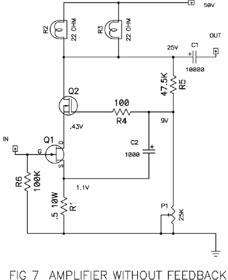
9 is where I get confused as it seems to have thrown the simple concept out and become much more complex, with three mosfets and a bjt and to be honest, I don't really understand what all of it actually does, so I was looking at more simple JFEtT circuits and found very little.
I'm not confident I could built a Zen 9 unless I had PCBs, laying it out on matrix board, is beyond my beginner level skills I think.
I did find this variation of the Zen 8 minus lightbulbs that looks fairly easy to build:

I'd want to reduce the supply voltage to 25v as that's what I happen to have available in transformers without buying something new, and that will make it a low power deice with less demanding thermal requirements (smaller heatsinks) so I was thinking of making it as a headphone amp and only later building a more powerful version using the knowledge I gained from building the lower power one.
I looked at the Zen 8 and 9 and they confuse me. 8 is simple but has two incandescent lightbulbs, which makes it unattractive to build:
9 is where I get confused as it seems to have thrown the simple concept out and become much more complex, with three mosfets and a bjt and to be honest, I don't really understand what all of it actually does, so I was looking at more simple JFEtT circuits and found very little.
I'm not confident I could built a Zen 9 unless I had PCBs, laying it out on matrix board, is beyond my beginner level skills I think.
I did find this variation of the Zen 8 minus lightbulbs that looks fairly easy to build:
I'd want to reduce the supply voltage to 25v as that's what I happen to have available in transformers without buying something new, and that will make it a low power deice with less demanding thermal requirements (smaller heatsinks) so I was thinking of making it as a headphone amp and only later building a more powerful version using the knowledge I gained from building the lower power one.
Attachments
You might try a really simple approach and just parallel more LU1014Ds for the output?
I made this as a headphone amp and it sounds quite nice. Now boost the current and provide lots of heatsinking. Increase output coupled cap of course. Perhaps even an inductor like 50mH in place of resistive loaf could work. Or even a CCS with and IRFP240 could work too.
I made this as a headphone amp and it sounds quite nice. Now boost the current and provide lots of heatsinking. Increase output coupled cap of course. Perhaps even an inductor like 50mH in place of resistive loaf could work. Or even a CCS with and IRFP240 could work too.
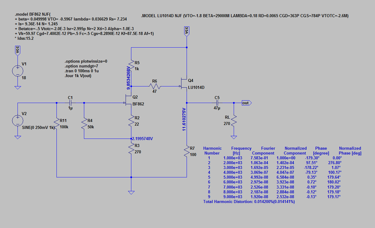
I like the look of that circuit, very simple and I have a few BF862s so I have the required parts.
Parallelling some LD1010Ds is definitely an option, perhaps something like Nelson Pass did to create his Beast of a 1000 FETs but with only 10 per channel?
Parallelling some LD1010Ds is definitely an option, perhaps something like Nelson Pass did to create his Beast of a 1000 FETs but with only 10 per channel?
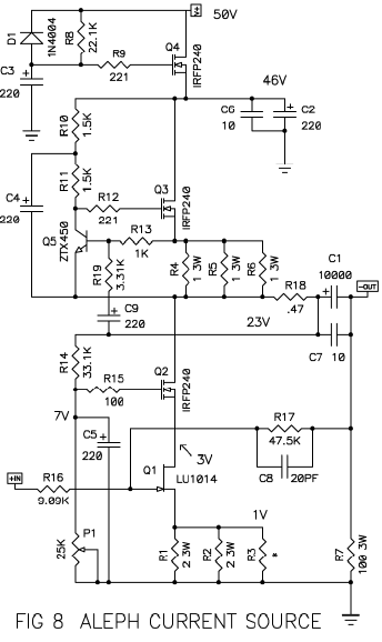
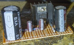
This is a rough sim that will get you a Fleawatt amp able to drive maybe 1.6wrms into 8ohms.
Bias current is 1.15A and dissipation is about 10w for all 5 LU1014D devices in parallel (or 2W ea, which is really about the max safe limit given how small the thermal pad is). Another 13.2W is dissipated by the 10R load resistor. Note that a clean and quiet 20vdc supply is easily obtained from a 24v SMPS followed by a MOSFET cap Mx which drops 4v. Gain is about 15dB.
This is 4Vpp into 8ohms gets 0.03% THD
8Vpp into 8ohms (1wrms) gets abotu 0.09% THD:
Bias current is 1.15A and dissipation is about 10w for all 5 LU1014D devices in parallel (or 2W ea, which is really about the max safe limit given how small the thermal pad is). Another 13.2W is dissipated by the 10R load resistor. Note that a clean and quiet 20vdc supply is easily obtained from a 24v SMPS followed by a MOSFET cap Mx which drops 4v. Gain is about 15dB.
This is 4Vpp into 8ohms gets 0.03% THD
Code:
Harmonic	Frequency	 Fourier 	Normalized	 Phase  	Normalized
 Number 	  [Hz]   	Component	 Component	[degree]	Phase [deg]
    1   	1.000e+03	2.030e+00	1.000e+00	 -179.95°	    0.00°
    2   	2.000e+03	5.166e-04	2.546e-04	  169.25°	  349.20°
    3   	3.000e+03	3.465e-04	1.707e-04	 -174.13°	    5.82°
    4   	4.000e+03	6.413e-06	3.160e-06	  -65.23°	  114.72°
    5   	5.000e+03	2.756e-06	1.358e-06	    5.20°	  185.15°
    6   	6.000e+03	6.009e-07	2.961e-07	   -6.61°	  173.34°
    7   	7.000e+03	4.824e-07	2.377e-07	   -0.45°	  179.50°
    8   	8.000e+03	4.421e-07	2.178e-07	    0.44°	  180.39°
    9   	9.000e+03	3.935e-07	1.939e-07	    0.06°	  180.01°
Total Harmonic Distortion: 0.030651%(0.030624%)
8Vpp into 8ohms (1wrms) gets abotu 0.09% THD:
Code:
Harmonic	Frequency	 Fourier 	Normalized	 Phase  	Normalized
 Number 	  [Hz]   	Component	 Component	[degree]	Phase [deg]
    1   	1.000e+03	4.052e+00	1.000e+00	 -179.95°	    0.00°
    2   	2.000e+03	2.164e-03	5.340e-04	  163.64°	  343.59°
    3   	3.000e+03	3.091e-03	7.627e-04	 -174.31°	    5.65°
    4   	4.000e+03	5.522e-05	1.363e-05	  -60.27°	  119.68°
    5   	5.000e+03	9.733e-05	2.402e-05	    6.75°	  186.71°
    6   	6.000e+03	1.561e-05	3.852e-06	  -79.48°	  100.47°
    7   	7.000e+03	7.455e-06	1.840e-06	 -170.20°	    9.76°
    8   	8.000e+03	2.977e-06	7.347e-07	   82.74°	  262.70°
    9   	9.000e+03	2.066e-06	5.099e-07	    6.39°	  186.34°
Total Harmonic Distortion: 0.093146%(0.093137%)
Attachments

Last edited:
Oh wow, that is exactly the sort of thing I had been looking for, many thanks indeed.
I have 10x LD1010D that I soldered to small PCB adapters, I could use those I think as even without a heatsink, they should manage the power dissipation I think.
It was after soldering this batch of 10 it occurred to me that heat might be a problem, so I bought 10 more and soldered them to pieces of copper 15x15mm, 1.5mm thick that I had drilled a 3mm hole in at top centre so they can be screwed/bolted to a heatsink.
So what I'm thinking is to build the design using the first batch on PCB adapters as a low power device, then later build a higher power version using the second batch soldered onto copper and bolted to heatsinks.
Funny you should mention a cap mx supply, I just happen to have built two of them using IRF640 MOSFETs, to this design:
Those should give a very low noise unregulated supply, I have spare toroidals I could use, one is dual 24V at 0.5A per winding, the other is dual 25v at 1A per winding, however, I also just bought a Meanwell 24V SMPS power brick that is rated for 40W, so I could follow your suggestion to use that as an external supply feeding the cap MX.
I also just built a pair of ripple eaters to this design but I used BC327-16 and BC337-16 trannies instead:

Not sure what I will do with them, I thought they might work well in conjunction with the Cap MX supplies. I've just built a pair of Camp Amp Class A boards and a pair of JLH 1969 'Atom BR' version Class A boards, so I wanted to try out different PSU solutions, hence I built the Cap MX and ripple eater boards, I also have boards I built using LT1083 regulators and a pair of L7824 regulator boards so I can play around with the different units and find what gives the best SQ with the simple Class A designs.
BTW, can I substitute a 6uF cap fr the 4.7uF on the input of your design? I happen to have some nice Italian made metal foil 6uF caps and no 4.7s at all. I take i I'll need to use a 15W resistor for R7, what about the other resistors - any of those need to be higher wattage types or can I use the usual 0.25-0.5w types?
I have 10x LD1010D that I soldered to small PCB adapters, I could use those I think as even without a heatsink, they should manage the power dissipation I think.
It was after soldering this batch of 10 it occurred to me that heat might be a problem, so I bought 10 more and soldered them to pieces of copper 15x15mm, 1.5mm thick that I had drilled a 3mm hole in at top centre so they can be screwed/bolted to a heatsink.
So what I'm thinking is to build the design using the first batch on PCB adapters as a low power device, then later build a higher power version using the second batch soldered onto copper and bolted to heatsinks.
Funny you should mention a cap mx supply, I just happen to have built two of them using IRF640 MOSFETs, to this design:
An externally hosted image should be here but it was not working when we last tested it.
Those should give a very low noise unregulated supply, I have spare toroidals I could use, one is dual 24V at 0.5A per winding, the other is dual 25v at 1A per winding, however, I also just bought a Meanwell 24V SMPS power brick that is rated for 40W, so I could follow your suggestion to use that as an external supply feeding the cap MX.
I also just built a pair of ripple eaters to this design but I used BC327-16 and BC337-16 trannies instead:
Not sure what I will do with them, I thought they might work well in conjunction with the Cap MX supplies. I've just built a pair of Camp Amp Class A boards and a pair of JLH 1969 'Atom BR' version Class A boards, so I wanted to try out different PSU solutions, hence I built the Cap MX and ripple eater boards, I also have boards I built using LT1083 regulators and a pair of L7824 regulator boards so I can play around with the different units and find what gives the best SQ with the simple Class A designs.
BTW, can I substitute a 6uF cap fr the 4.7uF on the input of your design? I happen to have some nice Italian made metal foil 6uF caps and no 4.7s at all. I take i I'll need to use a 15W resistor for R7, what about the other resistors - any of those need to be higher wattage types or can I use the usual 0.25-0.5w types?
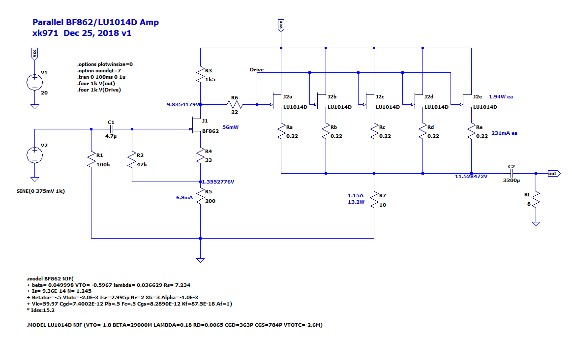
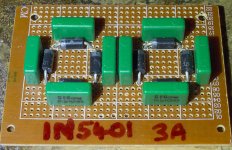
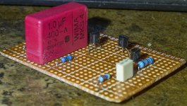
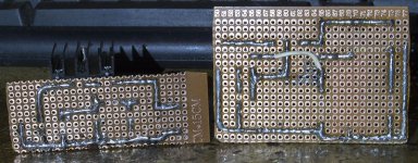
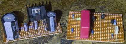
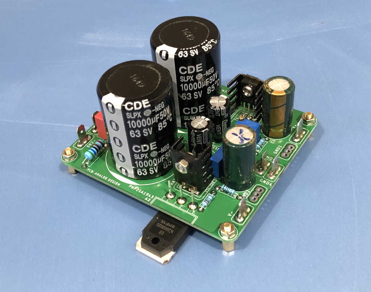
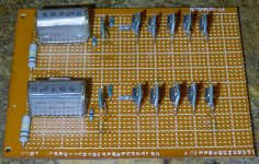
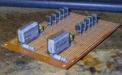
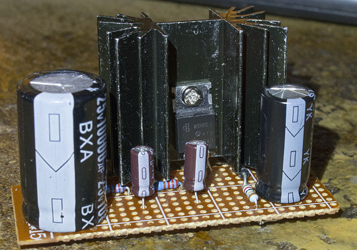
Here's some pics of the Cap MX and Ripple Eater I've built, I made two of each. I also made a couple of rectifiers using 1N5401 diodes and 0.1uF polypropylene caps.
The Cap MX is good for 25v as the 10000uF Rubycon on the right is rated 25v, as are the two small 47uF Nippon Chemi caps in the middle, the 1000uF Rubycon on the right is rated 50v. The diode is a 1N4004 and the resistors are Neohm LR1 0.6W and Vishay 0.5W. The MOSFET is an IRF640.
The ripple eater has a 1uF WIMA rated for 400v and a 0.47uF Arcotronics rated at 63V, the resistors are a mix of Neohm LR1 0.6w and Welyn 1W. Transistors are BC327-16 and BC337-16.
Attachments
Anywhere from 2.2uF to 10uF or more is fine. The 20v rail is important. Limits on voltages for these JFETs is low.
You can make the cap Mx as deadbug on legs of MOSFET, but the heatsink might need to be quite bigger. Just bolt TO-247 to main heatsink as 1.15A x 4v x 2ch is almost 10w. If dual cap Mx then 5w, still too big.
Juma's Easy-Peasy Capacitance Multiplier
You can make the cap Mx as deadbug on legs of MOSFET, but the heatsink might need to be quite bigger. Just bolt TO-247 to main heatsink as 1.15A x 4v x 2ch is almost 10w. If dual cap Mx then 5w, still too big.
Juma's Easy-Peasy Capacitance Multiplier
Last edited:
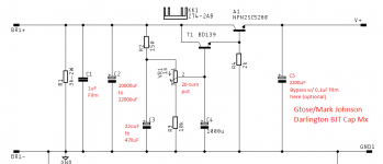
A little more complicated, but the Gtose/Mark Johnson cap multiplier using two BJTs works very well and has a lower voltage dropout (1.3v min and adjustable up to 2v-4v if desired). I have used this successfully in several amps now. Gerber files for PCBs are available or if you want to veroboard it, here is schematic (with some mods/notes in red) for just the positive side. Input is polarized output from bridge rectifier.
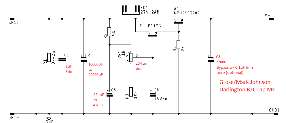
Dual-rail PCB version looks like this:
Dual-rail PCB version looks like this:
Attachments
Last edited:
Aah, so more heatsink mass required. I found a couple of much larger heatsinks in my parts stash that should do the job.
I'll build that Cap Mx at some point in the near future, it looks a fair bit more advanced than the very simple ones I already made.
I've made good progress in building the amp, can't finish it however as I don't have any 0.22 or 200 resistors, have to order some. I decided to use couple of RIFA 10uF caps as they fit nicely in the available space, I also added Evox MMK 0.1uF caps bypassing them.
Attachments

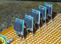
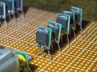
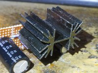
Each of those LU1014D’s needs to be installed on a heatsink of approximate size as what you have below (as they dissipate 2W ea). The little bars PCB you have on them block the metal thermal pad from contacting the heatsink. What I would recommend is to remove the little PCB boards and mount all 5 on a common 10W capable heatsink (about 50mm x 125mm x 25mm fins). Clamp all 5 down with a bar clamp with threaded holes in between each. Use a single layer of Kapton tape as insulator or individual TO220 silicone pads.
If you leave them as is without a heatsink, they will melt at 2W ea.
Ea needs heatsink like this if done individually.
If you leave them as is without a heatsink, they will melt at 2W ea.
Ea needs heatsink like this if done individually.
Hmm, I need to have a rethink then, I'll have a look at what pieces of aluminium and heatsink I have in my shed and figure something out.
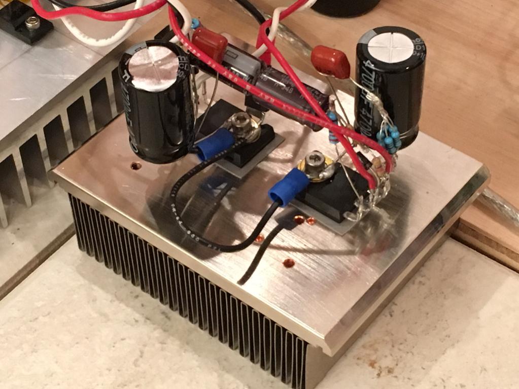
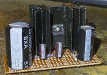
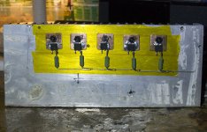
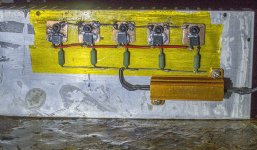
Due to family issues, progress has been rather slow, but I'm finally getting somewhere; I've soldered the L1010Ds to 15mmx15mm 1mm thick copper shims that I have then bolted to a nice big chunk of aluminium - 18x8cm and 25mm thick (7.25x3 inches, 1 inch thick) which should be ample to soak up the heat. The yellow stuff is kapton tape and I used nylon nuts and bolts so the copper is elctrically isolated from the aluminium. I'm working on the chassis now.
BTW, is the big resistor that is going to have to handle 13.5W there to control the current? If so, would it be feasible to replace it with a CCS?
BTW, is the big resistor that is going to have to handle 13.5W there to control the current? If so, would it be feasible to replace it with a CCS?
Attachments
Pardon my ignorance but what are SRPP and circlotrone? Are they amp designs? If so, I'd love to see what you come up with. These LD1010Ds are cheap so it's not a great expense to play around with various designs using them.
Here is where I got them:
10pcs LDI010D LD1O10D LD10I0D LD101OD LD1010O LD1010D TO252 Transistor | eBay
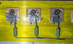
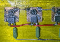
Here's how far I have got today with putting this amp together, forgive the terribly ugly soldering on the copper pads, they were bloody difficult to solder. The resistor is a 50watter, which is overkill but better too big than too small!
Here is where I got them:
10pcs LDI010D LD1O10D LD10I0D LD101OD LD1010O LD1010D TO252 Transistor | eBay
Here's how far I have got today with putting this amp together, forgive the terribly ugly soldering on the copper pads, they were bloody difficult to solder. The resistor is a 50watter, which is overkill but better too big than too small!
Attachments
- Status
- Not open for further replies.
- Home
- Amplifiers
- Solid State
- Simple Class A Amp using JFET Output Devices