Hi
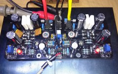
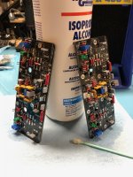
I got my v4h boards and the parts a while back. I have now started to put in the components together. I accidentally touched the soldering Iron to one of the 100nf 100v cap. should I replace it?
Bharat Singh
I think your cap is ok , but judging by the way your boards look I think you’ll always think about that cap. Go ahead an replace it, messes up the perfect look of your work!
I think your cap is ok , but judging by the way your boards look I think you’ll always think about that cap. Go ahead an replace it, messes up the perfect look of your work!
Thanks for suggestion. Yes you are right once have seen it I can't unsee it. It definitely is a eye sore, will probably replace it once I have put all the remaining parts in as I may mess up some more😀
Bharat Singh
UPDATE: Output Stage Oscillation When Signal Volume Increased - SOLVED
Hello Members.
Since mid August I have been receiving a few reports of the amplifier setting up normally but running into oscillation and overheating as soon as the music volume is slightly increased. The sound is crackling and noisy with high current draw from power supply. No report of catastrophic failure, but it has been annoying the builders. Generally the suggested solution was to replace the 5W resistors with 2W ones, but even this didn't help a couple cases.
While I didn't face the same problem beforehand in my builds, recently after my last bunch of 5W resistors was exhausted I ordered another bunch. These were same value but from different manufacturer. And during tests was faced by the very same problem of oscillation with signal input.
I isolated the oscillation to the output section and tried whatever I could to make it go away. After a month of experiments, today evening it went away. 🙂
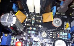
The culprit is the unequal gate-source capacitance of the N and P channel MOSFETs - the 2SK1058 has 600pF between gate and source pins while the 2SJ162 has 900pF.
Installed a 270pF 500V ceramic capacitor between the gate and source pins of each of the N MOSFETs (on the positive side of the board), and that's all. Now the amp is fully tame and calm. I cranked up the volume and gradually ran it right into clipping with music and no hint of oscillation in the scope. No crackle, no noise, no heat, just music, with the same 5W resistors that are very inductive.
I'm a bit embarassed because it's a very commonplace and effective trick. I wonder why it didn't struck me earlier 😱. I understand that in an otherwise well sounding amplifier this kind of problems are quite unwelcome and I apologize to everyone who faced it during their build. In the next bunch of V4H boards there will be accomodation for the two capacitors.
Thanks for your time.
shaan
Hello Members.
Since mid August I have been receiving a few reports of the amplifier setting up normally but running into oscillation and overheating as soon as the music volume is slightly increased. The sound is crackling and noisy with high current draw from power supply. No report of catastrophic failure, but it has been annoying the builders. Generally the suggested solution was to replace the 5W resistors with 2W ones, but even this didn't help a couple cases.
While I didn't face the same problem beforehand in my builds, recently after my last bunch of 5W resistors was exhausted I ordered another bunch. These were same value but from different manufacturer. And during tests was faced by the very same problem of oscillation with signal input.
I isolated the oscillation to the output section and tried whatever I could to make it go away. After a month of experiments, today evening it went away. 🙂
The culprit is the unequal gate-source capacitance of the N and P channel MOSFETs - the 2SK1058 has 600pF between gate and source pins while the 2SJ162 has 900pF.
Installed a 270pF 500V ceramic capacitor between the gate and source pins of each of the N MOSFETs (on the positive side of the board), and that's all. Now the amp is fully tame and calm. I cranked up the volume and gradually ran it right into clipping with music and no hint of oscillation in the scope. No crackle, no noise, no heat, just music, with the same 5W resistors that are very inductive.
I'm a bit embarassed because it's a very commonplace and effective trick. I wonder why it didn't struck me earlier 😱. I understand that in an otherwise well sounding amplifier this kind of problems are quite unwelcome and I apologize to everyone who faced it during their build. In the next bunch of V4H boards there will be accomodation for the two capacitors.
Thanks for your time.
shaan
Attachments
Last edited:
Hello Members.
Since mid August I have been receiving a few reports of the amplifier setting up normally but running into oscillation and overheating as soon as the music volume is slightly increased. The sound is crackling and noisy with high current draw from power supply. No report of catastrophic failure, but it has been annoying the builders. Generally the suggested solution was to replace the 5W resistors with 2W ones, but even this didn't help a couple cases.
While I didn't face the same problem beforehand in my builds, recently after my last bunch of 5W resistors was exhausted I ordered another bunch. These were same value but from different manufacturer. And during tests was faced by the very same problem of oscillation with signal input.
I isolated the oscillation to the output section and tried whatever I could to make it go away. After a month of experiments, today evening it went away. 🙂
The culprit is the unequal gate-source capacitance of the N and P channel MOSFETs - the 2SK1058 has 600pF between gate and source pins while the 2SJ162 has 900pF.
Installed a 270pF 500V ceramic capacitor between the gate and source pins of each of the N MOSFETs (on the positive side of the board), and that's all. Now the amp is fully tame and calm. I cranked up the volume and gradually ran it right into clipping with music and no hint of oscillation in the scope. No crackle, no noise, no heat, just music, with the same 5W resistors that are very inductive.
I'm a bit embarassed because it's a very commonplace and effective trick. I wonder why it didn't struck me earlier 😱. I understand that in an otherwise well sounding amplifier this kind of problems are quite unwelcome and I apologize to everyone who faced it during their build. In the next bunch of V4H boards there will be accomodation for the two capacitors.
Thanks for your time.
shaan
Hi Shaan,
Interesting, I saw that for the Exicon Ciss is 500pF for both P and N.
Is it better ?
Is the fact that it's lower than 900pF a problem ?
Hi Shaan,
Interesting, I saw that for the Exicon Ciss is 500pF for both P and N.
Is it better ?
I think it is. The extra caps probably won't be necessary with exicons.
Is the fact that it's lower than 900pF a problem ?
Not at all.
Hi,
which power resistors (0.1R 5W) you choose for this amp? Can you give order code'
Thanks,
Sorry, no order code. I found them on ebay for cheap. Same size as shaan used. Hard to find same size on mouser(which i used for rest of board). Try "cement 5w resistor" for searching ebay.
Will add caps on my boards when i recive new pcb. Perhaps this is whats been troubling me? One of my channels would suddently consume 400ma/rail and output 1-4vDC. This happend after 30 min - no load/signal, or when increasing current over 230ma/rail.
which power resistors (0.1R 5W) you choose for this amp? Can you give order code
I purchased these for R35-38: 0.1 ohm 5% 5W Power Resistor, Qty 10 | eBay.
These from DigiKey also seem like they would work: MPR5JBR100 Stackpole Electronics Inc. | Resistors | DigiKey
The Digikey resistors are not wire wound, which might help.
I cannot try them as I am still waiting for other parts to arrive, hopefully before Christmas.
Shaan that's an easy fix for the guys that are using Renesas outputs and thanks for the update.
I cannot try them as I am still waiting for other parts to arrive, hopefully before Christmas.
Shaan that's an easy fix for the guys that are using Renesas outputs and thanks for the update.
This might be voodoo or black magic but I do not use steel screws/ washers on the output devices.
I only use stainless steel or brass which are not attracted to magnets.
I only use stainless steel or brass which are not attracted to magnets.
...Will add caps on my boards when i recive new pcb. Perhaps this is whats been troubling me? One of my channels would suddently consume 400ma/rail and output 1-4vDC. This happend after 30 min - no load/signal, or when increasing current over 230ma/rail.
Yes these are the symptoms. The oscillation frequency is around 1MHz and around 6VPP, bias increases to 300-400mA and offset increases to 4-5V.
The Digikey resistors are not wire wound, which might help. I cannot try them as I am still waiting for other parts to arrive, hopefully before Christmas.
I arranged V4H's output so that it welcomes highly inductive resistors as well as non-inductive ones. Don't worry about wirewound, these work fine.
Shaan that's an easy fix for the guys that are using Renesas outputs and thanks for the update.

This might be voodoo or black magic but I do not use steel screws/ washers on the output devices.
I only use stainless steel or brass which are not attracted to magnets.
As my tests showed, magnetic resistor element or mounting screws made from ferromagnetic metals have no effect on the amp's stability. Initially I too did suspect those, but after a series of experiments found no relation. Ultimately it all came down to the balance of gate capacitance between the MOSFETs. After balance has been achieved, the amp becomes quite dead towards external disturbances except the input signal. 🙂
Will add caps on my boards when i recive new pcb...
You can use 1206 series SMD caps on your existing boards for minimum footprint. 270pF 50V will suffice.
Hello Members.
Since mid August I have been receiving a few reports of the amplifier setting up normally but running into oscillation and overheating as soon as the music volume is slightly increased. The sound is crackling and noisy with high current draw from power supply. No report of catastrophic failure, but it has been annoying the builders. Generally the suggested solution was to replace the 5W resistors with 2W ones, but even this didn't help a couple cases.
While I didn't face the same problem beforehand in my builds, recently after my last bunch of 5W resistors was exhausted I ordered another bunch. These were same value but from different manufacturer. And during tests was faced by the very same problem of oscillation with signal input.
I isolated the oscillation to the output section and tried whatever I could to make it go away. After a month of experiments, today evening it went away. 🙂
The culprit is the unequal gate-source capacitance of the N and P channel MOSFETs - the 2SK1058 has 600pF between gate and source pins while the 2SJ162 has 900pF.
Installed a 270pF 500V ceramic capacitor between the gate and source pins of each of the N MOSFETs (on the positive side of the board), and that's all. Now the amp is fully tame and calm. I cranked up the volume and gradually ran it right into clipping with music and no hint of oscillation in the scope. No crackle, no noise, no heat, just music, with the same 5W resistors that are very inductive.
I'm a bit embarassed because it's a very commonplace and effective trick. I wonder why it didn't struck me earlier 😱. I understand that in an otherwise well sounding amplifier this kind of problems are quite unwelcome and I apologize to everyone who faced it during their build. In the next bunch of V4H boards there will be accomodation for the two capacitors.
Thanks for your time.
shaan
Hi shaan,
Does this problem occurs with V2 also, l had one board failure after set up , and another one looks OK , can you confirm this
No I did not face the problem in V2. Unfortunately I don't have any V2 boards to test. The effect of these capacitors on sonics is zero and if anything they won't make the amp unstable. So if you are thinking of adding them to your boards then feel free to do so.
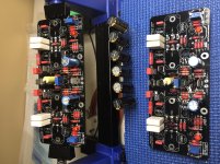
I finally got a bit of time to start the V4H amplifier boards🙂
Shaan,
From the start, I installed the 270pF caps to guard against potential oscillation like you had discussed.
Shaan,
From the start, I installed the 270pF caps to guard against potential oscillation like you had discussed.
Attachments
Hi Vunce.
Are you sure these are 270pFand not 27pF? If I'm not missing something they sould have 271 marked for 270pF.
Are you sure these are 270pFand not 27pF? If I'm not missing something they sould have 271 marked for 270pF.
The CDM capacitors have two type or markings for 220pf it will be 220+-5% or 221j
The above cap should be correct 270pf.
But why are c21 and c22 different from all other 110nf cap?
Bharat Singh
The above cap should be correct 270pf.
But why are c21 and c22 different from all other 110nf cap?
Bharat Singh
Last edited:
Hi Vunce.
Are you sure these are 270pFand not 27pF?
Hi Shaan,
They indeed are 270pF Cornell Dubilier mica caps. Bharat is correct, that’s how CDE labels them.
C21/22 are Wima 100nF MKP’s, the others are MKS (same value but smaller).
Hi Shaan,
They indeed are 270pF Cornell Dubilier mica caps. Bharat is correct, that’s how CDE labels them.
C21/22 are Wima 100nF MKP’s, the others are MKS (same value but smaller).
Hi,
I read that MKT are better than MKP for decoupling ? Any advices ?
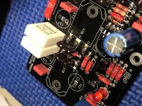
Very nice as usual Vunce! I started mine this week as well, we are twinsies with our PRP red resistors! I went with Vishay MKT370 for my film caps (BFC237022104 Vishay BC Components | Capacitors | DigiKey). I'll be using Exicons, so I believe I will not have to add the N MOSFET caps?
Greg
Greg
Attachments
- Home
- Group Buys
- PeeCeeBee V4H GB