How you measure your RIAA curve? Using anti Riaa input filter, then checking with gen and scope for amplitude VS frequency?
yep. That is how I do it; but it is rough because the Toellner 7402 freq generator I have is based on a chip and at low freq there are steps due to probably a wirewound resistor. So it is quite elementary.
My 2SK240/ECC88, 6SL7 double cascode RIAA build
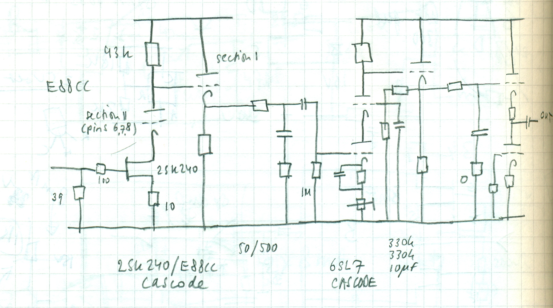
Maybe I missed something about the above schematic. What happened to the grid of the first triode? Shouldn't there be a voltage supply to the E88CC grid?
Maybe I missed something about the above schematic. What happened to the grid of the first triode? Shouldn't there be a voltage supply to the E88CC grid?
to ground
to ground
No, the Vds of the FET would be too low. I'd rather tie it to a voltage divider to run the FET at 5-7V Vds. Plus you can try the Brosky trick by wiring the smoothing cap to V+ instead of ground.
"To ground" for the AF signal and a +7-9 Volts, depending of the working point of the second part of the ecc88.
2 resistors from the +B to earth, the second trimmer and 0.1 - 1 uF film from grid to earth.
2 resistors from the +B to earth, the second trimmer and 0.1 - 1 uF film from grid to earth.
Will using a CCS for plate load increase PSRR of the FET/tube cascode?
Also arent most JFETs least noisy with low drain voltage?
BF862 works happy at < 3V.
Also arent most JFETs least noisy with low drain voltage?
BF862 works happy at < 3V.
Yes it would, but the CCS needs to have high output impedance too: if it's the same as the cascode, then you get -6dB. Also, the plate voltage is not well defined because it's at the junction of 2 active devices. Instead of adding more silicon to the circuit, I prefer an overkill power supply: the one I'm working on has a 6th order LCLCRCRC filter after the tube rectifier; that should be quiet enough.
I'm not familiar with the BF862, so I can't say when it's happy, or not. The Toshiba 2SK146/147 I use have a fairly flat NF vs Vds curve, starting at about 3.2dB at Vds = 5v, droping to a minimum of about 2.9dB at 25V, and raising again to about 3.7dB at 50V. However, if you look at the Id vs Vds curve, the knee starts at about .5V until about 3V where it flattens out. That's why I prefer to run it at 5-7V to keep it in its linear region.
With that, I must admit that initially, I was very tempted to return the grid to ground for its simplicity.
Last edited:
- Status
- Not open for further replies.
- Home
- Source & Line
- Analogue Source
- A two-stage MC tube based RIAA circuit