Correct. The DC input on the +input of a se CFA does not materially affect the signal operation although it will affect the DC offset at the output.
The operation itself is controlled by the various current converging at the -input and summing to zero, as discovered by Mr. Kirchhoff ;-)
Jan
The operation itself is controlled by the various current converging at the -input and summing to zero, as discovered by Mr. Kirchhoff ;-)
Jan
I choose a simple circuit which manifestly belongs to the family of today's called CFAs and compare your analysis to mine. We agreed on some points, it is not bad.
forr, maybe I would better understand your views if you could explain why I should apply your voltage/transconductance paradigm to the attached circuit. Also, I'd appreciate it if you could advise me how you embed an image in text rather than attaching it. I see the tag but don't know how to upload the image. Your help would be appreciated.
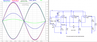
We use E2 to help measure the U1 input stage transresistance r. It can be seen to be 13.2k / ( 1/(1000_v_diff /1000) - 1) = 53 ohms.
In the U1 circuit, 13.2k is much larger than the transresistance r = 1/gm. U1's operation is almost completely insensitive to the value of r. r could be set to zero or multiplied by 10, and it would hardly matter. The value of r is almost completely irrelevant to circuit operation.
The three op amps' AC output voltages can be seen to be virtually identical, as are the AC inverting input currents. Therefore, it is reasonable to expect that the modes of operation of the three circuits are very similar.
Claims of significant differences would have to be justified.
In the absence of evidence to the contrary, the operations of U2 and U3 should be similarly insensitive to the value of r. This is confirmed by the simple fact that the design equations for CFAs ignore r. In fact, many CFA data sheets don't even specify r!
So why should we prefer an explanation of CFA operation that depends on voltage, which requires the transconductance parameter 1/r = gm, when the value of gm has so little effect on circuit performance?
It can be easily verified by opening the feedback loop that the CFA can be described as a transresistance amplifier for which Vout = Z x I. With the loop closed, inverting input current I is linearly related to the current into/out of the output stage.
With no resistor to ground, all output stage current flows into the input stage and in the same direction as that current, clearly implementing positive current feedback. The relative current directions must be reversed for negative current feedback. The addition to this simple circuit of a single resistor or a network of resistors to ground allows this directional change. This changes circuit operation from positive to negative current feedback.
Attachments
Voltage feedback vs Current feedback
https://www.ieee.li/pdf/viewgraphs/current_feedback_vs_voltage_feedback_amplifiers.pdf
-RNM
Yes, I've seen this before. It's a good presentation. I would call your and everyone's attention to slides 9 through 11, which use the term "current feedback" to describe OTA's and "Current Feedback Amplifiers" (that last in big red type.)
In a nod to your preferred use of the term, slide 5 also mentions "voltage mode or current mode."
The problems here are several.
1. There is a configuration called a "Norton" amplifier that actually is a current input amplifier ~LM3900.
2. Some audio amps have used a series resistor or transformer to sense the output current and effect an artificially high output impedance, ie actual 8 Ohms, a buffering factor of one. This has the advantage of controlling speaker "series" resonances. You could just put a 8 Ohm resistor in series with the speaker but that would waste 3/4 of the potential output power, ie half of the 16 Ohm power. In any case, what the semi industry is calling CFAs is something completely different. A "CFA" does not sense the output current.
3. A CFA bandwidth can be reduced by putting a resistance in the negative feedback (emitter circuit) and you could call that a "feature", but you can also do that to VFAs by shunting the inputs. Either way, you are just deliberately wasting gain because the amp is not stable at the gain you need.
4. The only real advantage to CFAs is that it reduces the number of poles in the feedback loop and therefore improves the potential bandwidth and/or stable amount of feedback. This comes at the cost of b-e junction input distortion unless that distortion is cancelled by a fully complementary amplifier, ie a PNP CFA plus a NPN CFA, or perhaps, a FET input transistor.
5. So, yes the term CFA is an unfortunate precedent that will confuse those who live at the black box model level, oblivious of the detail inside. I would have called it something like a semi-differential amp.
I must disagree. Please see my next post to forr.
You can disagree. In this case you are wrong.
Current on a transistor is always related to the Vbe or Vgs value.
If you move the voltage applied to the gate of J1, the voltage on the source, which is output, move by the same quantity.
If I bias the gate of J1 to -20V, there will be no current in the transistor because you cannot have the right voltage value on the source.
The problems here are several.
1. There is a configuration called a "Norton" amplifier that actually is a current input amplifier ~LM3900.
2. Some audio amps have used a series resistor or transformer to sense the output current and effect an artificially high output impedance, ie actual 8 Ohms, a buffering factor of one. This has the advantage of controlling speaker "series" resonances. You could just put a 8 Ohm resistor in series with the speaker but that would waste 3/4 of the potential output power, ie half of the 16 Ohm power. In any case, what the semi industry is calling CFAs is something completely different. A "CFA" does not sense the output current.
3. A CFA bandwidth can be reduced by putting a resistance in the negative feedback (emitter circuit) and you could call that a "feature", but you can also do that to VFAs by shunting the inputs. Either way, you are just deliberately wasting gain because the amp is not stable at the gain you need.
4. The only real advantage to CFAs is that it reduces the number of poles in the feedback loop and therefore improves the potential bandwidth and/or stable amount of feedback. This comes at the cost of b-e junction input distortion unless that distortion is cancelled by a fully complementary amplifier, ie a PNP CFA plus a NPN CFA, or perhaps, a FET input transistor.
5. So, yes the term CFA is an unfortunate precedent that will confuse those who live at the black box model level, oblivious of the detail inside. I would have called it something like a semi-differential amp.
You've obviously done some looking into this. I actually did number 3 in my AudioXpress article which can be read at Current Feedback: Fake News or the Real Deal? | audioXpress .
You can disagree. In this case you are wrong.
Current on a transistor is always related to the Vbe or Vgs value.
If you move the voltage applied to the gate of J1, the voltage on the source, which is output, move by the same quantity.
If I bias the gate of J1 to -20V, there will be no current in the transistor because you cannot have the right voltage value on the source.
That's not what I disagreed about. Sorry, I would rather focus on my discussion with forr.
This is not correct. In a standard DB, the input and buffer transistor Vbe's cancel so that Vi+ and Vi- are equal when operating in the linear mode.
Vbe does not enter into the equation (even if you remove Re and just rely on the internal emitter resistance re') And, in a 'single ended CFA' the Vbe does not materially affect the fundamental operation in which a current (+ or -) is injected into the inverting input (IMPORTANT: this is where Rf, Rg and Re all meet) in order to balance the summing junction currents.
Any transistor current variation is related to a Vbe or Vgs variation.
It's a law of physics.
Any transistor current variation is related to a Vbe or Vgs variation.
It's a law of physics.
yup.
Any transistor current variation is related to a Vbe or Vgs variation.
It's a law of physics.
Agree. But in a DB or an LTP you do not need to invoke the Vbe vs collector current to describe the operation of an amplifier at system level. After all, do you do that when you apply an opamp? No, you simply apply the correct feedback and gain formulas and you can completely and accurately predict the circuits performance.
There are some extraordinary mental gymnastics on display here to try to circumvent the current operating principle of a CFA, or 'transmute' it into a VFA for want of a better word. The test of your approach is 'can it accurately characterize the performance of a CFA in the same manner that the conventional CFA analysis does?'. I don't think so.
Any transistor current variation is related to a Vbe or Vgs variation.
It's a law of physics.
Of course. Take the example of a common-base stage. The input is a current into the emitter. That current changes the Vbe value. But the input is a current, nevertheless.
Interestingly, seen from the inv input of a CFA, you are looking at a common base stage ;-)
Jan
Agree. But in a DB or an LTP you do not need to invoke the Vbe vs collector current to describe the operation of an amplifier at system level. After all, do you do that when you apply an opamp? No, you simply apply the correct feedback and gain formulas and you can completely and accurately predict the circuits performance.
There are some extraordinary mental gymnastics on display here to try to circumvent the current operating principle of a CFA, or 'transmute' it into a VFA for want of a better word. The test of your approach is 'can it accurately characterize the performance of a CFA in the same manner that the conventional CFA analysis does?'. I don't think so.
We are not applying an opamp, but discussing the CFA term.
As transistors are voltage driven, What is called CFA are not current feedback amplifier.
A VFA input stage is only a CFA input with a buffer. Then the differences are : one more pole on VFA and the fact that open loop CFA gain depends on feedback network.
Of course. Take the example of a common-base stage. The input is a current into the emitter. That current changes the Vbe value. But the input is a current, nevertheless.
Interestingly, seen from the inv input of a CFA, you are looking at a common base stage ;-)
Jan
A common base stage is voltage driven on a low impedance input.
As transistors are voltage driven, what is called CFA are not current feedback amplifier.
This is really bizarre non-logic.
Jan
A common base stage is voltage driven on a low impedance input.
Well you wouldn't say that if you had ever build a common base stage.
You will probably still say that it is voltage driven even if I drive it from a 100GOhm current source.
Let me ask you. You are throwing up one-line statements. Is there something you want to explain to us, make a point? If so, what is it? Are you able to present a logical, reasoned argument or will it stay just one-liners? I got more things to do.
Jan
Last edited:
If you try to explain a CFA as a VFA minus half an LTP (which you called a ‘buffer’) you have completely misunderstood the operating principle of a CFA. Sorry, i do not want to offend you but I can put it in no other way.
Please keep in mind you are trying to argue your case against the combined experience of 30+years of application expertise across the semiconductor industry and against academia as well (see for example Prof. Sergio Franco’s description of CFA operation).
In any case, clearly if smarter and more experienced people have failed to convince you, I will not be able to.
Adieu!
Well you wouldn't say that if you had ever build a common base stage.
I did. At least one time for a simple adder.
You will probably still say that it is voltage driven even if I drive it from a 100GOhm current source.
I designed photo diodes current amplifier asic in cmos .35µm techno, would you say that mos transistors are current driven ?
Let me ask you. You are throwing up one-line statements. Is there something you want to explain to us, make a point? If so, what is it? Are you able to present a logical, reasoned argument or will it stay just one-liners? I got more things to do.
Jan
Not sure to understand.
The only interest is to know if what is written is true or not , not the length of the post. If you have more interesting things to do, please, don't reply.
Can you consider also that I am left handed 😱 and english is not my native language so my posts could be unintentionally clumsy
My point is that transistors are voltage driven components.
In what you call CFA, the inverting input is driven by a fraction of output voltage. The only difference with VFA is that the inverting input low impedance is part of the feedback network.
As forr said, the first stage of a closed loop amplifier make the difference between input voltage and something that come from the output.
As far I know you cannot make the difference between a voltage and a current.
If you try to explain a CFA as a VFA minus half an LTP (which you called a ‘buffer’) you have completely misunderstood the operating principle of a CFA. Sorry, i do not want to offend you but I can put it in no other way.
Please keep in mind you are trying to argue your case against the combined experience of 30+years of application expertise across the semiconductor industry and against academia as well (see for example Prof. Sergio Franco’s description of CFA operation).
In any case, clearly if smarter and more experienced people have failed to convince you, I will not be able to.
Adieu!
It is not a problem nore the first time I misunderstand something.
I do not want to offend you but I have to recall that the only argument you oppose to my assert was wrong.
The name of what you are doing is "authority arguments" : no value.
Of course. Take the example of a common-base stage. The input is a current into the emitter. That current changes the Vbe value. But the input is a current, nevertheless.
Another thought experiment, take the standard one stage CFA (the usual simplified schematic) and substitute an ideal voltage to current converter for the feedback resistor. That is force literal current feedback.
Yes, I've seen this before. It's a good presentation. I would call your and everyone's attention to slides 9 through 11, which use the term "current feedback" to describe OTA's and "Current Feedback Amplifiers" (that last in big red type.)
In a nod to your preferred use of the term, slide 5 also mentions "voltage mode or current mode."
Well, I put that up for a couple of pictures in it that relates to my question as to what happens when you apply a Cf across the Rf in a CFB and in a VFB amp.
On a VFB amp, it would roll off the frequency response. It does just the opposite in a CFB amp. Peaking and ringing and osc.
I thought that might help some to rethink their arguments on how CFB work.
THx-RNMarsh
Last edited:
- Home
- Amplifiers
- Solid State
- Current Feedback Amplifiers, not only a semantic problem?