Another view.
Take, to simplify, a so-called CFA (sorry, for the so-called, I can't agree with the CFA naming) using a single transistor input stage.
When the feedback network is not connected to the output stage, the load seen by the emitter of the input transistor is only that of the bottom resistor of the feedback network which usually is of a low value, 100 to 1000 Ohm typically.
When the feedback is connected to the output stage, the AC current through the bottom resistor is highly increased, so the emitter sees a much higher impedance. The whole functionning is mainly under the control of the base emitter voltage (Vbe) of the input transistor.
It reminds me the operation of Sziklai pairs, bootstrapped or current dumping circuits where an AC current, synchronised with the input signal through feedback, enhances the impedance of the load seen by their output.
In CFAs, the inverting input can be considered as a local output which is not the case in a VFA where the inverting input has a very high impedance and does not deliver current.
A "current feedback amplifier” (CFA) seems more appropriated describable as a “dynamic transconductance amplifier” (DTA) with a buffered output. This is for the following reasons.
In the case of an ideal CFA the input unity gain buffer has zero output impedance. Hence the output voltage of the input buffer would not be affected by any network attached to it. This means that the "non-inverting input terminal" can be more accurately identified as a "current sensing output terminal” or in the brevity a "current sensing terminal" or "CST". It is suspected that the identification of the inverting input terminal has contributed most to the difficulty of comprehending the manner of its function, being an output and not an input.
This indicates that the CST imposes dynamically immutable voltages to whatever resistance network is attached. The current being sensed by the CST is solely dependant upon whatever current results from applying this voltage to a point in the network. This is independent of feedback. Under circumstances whereupon either the CST voltage is dynamically varied, or the voltage on the other end of a resistance network is variant the device can be characterized as a transconductance amplifier with a buffered output.
Under conditions whereupon a multiplicity of dynamically variant voltages are imposed, as is the case in feedback networks, the equivalent resistance and transconductance becomes dynamically variant. This supports the characterization of these devices as dynamic transconductance amplifiers or “DTA's”.
I wrote
Just let's recall that this term appears in the eighties with integrated amplifying circuits having an inverting input made of the two emitters of complementary transistors.The input impedance of this inverting input is low.
Just as it is for amplifiers having a single input devices : most tube amps and transistors amps until 1975 were never said to be CFAs.
Some great engineers (one of them having a very well known name) complained of this for two reasons :
1. Current Feedback had an other meaning
2. an amplifier having a low impedance inverting input is nevertheless under the control of voltage.
This has been already discussed a lot.
For a further step, I proposed a recent amplifier by Jean-Marc Plantefève.
I think that because of its simplicity, it coud help people to make their own idea about the validity of the concept of CFA.
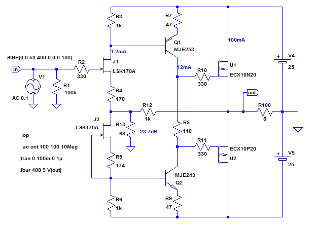
Resistor R4 is probably there for DC reasons and could be bypassed by an electrolytic capacitor to simplify a theorical discussion about the input stage.
To transforn the circuit to a VFA, a JFET, J3, needs to be added, its source coupled to the J1 source and its gate connected to the feedback node. Maybe the constant current delivered by J2 would need adjustment for adequate DC conditions.
The role of J3 is then to buffer the feedback voltage across R13.
The two topologies can now be compared without complications.
to attract the attention of the members who have not read the full thread to the fact that the naming and the interpretation of Current Feedback Amplifiers is a subject of controversies.so-called CFA (sorry, for the so-called, I can't agree with the CFA naming)
Just let's recall that this term appears in the eighties with integrated amplifying circuits having an inverting input made of the two emitters of complementary transistors.The input impedance of this inverting input is low.
Just as it is for amplifiers having a single input devices : most tube amps and transistors amps until 1975 were never said to be CFAs.
Some great engineers (one of them having a very well known name) complained of this for two reasons :
1. Current Feedback had an other meaning
2. an amplifier having a low impedance inverting input is nevertheless under the control of voltage.
This has been already discussed a lot.
For a further step, I proposed a recent amplifier by Jean-Marc Plantefève.
I think that because of its simplicity, it coud help people to make their own idea about the validity of the concept of CFA.
Resistor R4 is probably there for DC reasons and could be bypassed by an electrolytic capacitor to simplify a theorical discussion about the input stage.
To transforn the circuit to a VFA, a JFET, J3, needs to be added, its source coupled to the J1 source and its gate connected to the feedback node. Maybe the constant current delivered by J2 would need adjustment for adequate DC conditions.
The role of J3 is then to buffer the feedback voltage across R13.
The two topologies can now be compared without complications.
Last edited:
What does the extremely elusive and opaque term "electric current" signify in the first place?
Electron density?
Electric charge density?
Electric mass density?
Is it an electrostatic property?
Is it a signal property?
Is it a scalar quantity?
Is it a vector quantity?
What in the hell is flowing?
Is it a physical substance or a metaphysical essence?
Does the naming justify the notion?
Considering the conceptual and semantical severity of the subject, the exploration may require another seven hundred posts.
More than usually, the naming describes the function, not the topology.Does the naming justify the notion?
For years, CFA used to mean that the value under control at the output of an amplifier is Current.
The CFA naming appears with the emergence of push-pull versions of an ancient and very common topology. It only refers to an interpretation of the way this topology works.
Some people I am part of do not adher to this intepretation which resorts to complicated arguments. Looking at the basic operation (Emitter Follower, Common Base...) of the devices assuming the subtraction process, the core of feedback, says otherwise.
Last edited:
A nice introduction I've found to the CFA vs VFA topic is this one: https://www.renesas.com/us/en/www/doc/application-note/an1993.pdf
I always try help myself by the notion that a VFA can be conceptually modelled as a CFA with buffered -IN driving a fixed impedance (unaccessible resistor in case of chips), whereas with a CFA the -IN node impedance is user-accessible and the standard gain divider compensates itself for bandwith vs gain as OLG goes up when impedance goes down (Ri_-in << Rg << Rf).
All the differences can be derived from that. A typical real example of that modelling is the LT1364. But the principle also applies to standard VFA input diff-amp topologies.
I'm fine with the naming conventions, they are just that, names. More important are the models in your mind you associate that with...
Last edited:
Forget acronyms and names for the moment. Forget the question of control. The word feedback implies that "something" is routed "back" to "something else."
In assigning nomenclature to a circuit, let us first identify the "something" and then the "something else." Nomenclature should now flow naturally. If the assigned nomenclature is inconsistent with what has been identified, then although we may have an historical precedent, we also have a technical inaccuracy.
Let's go back to basics. In any circuit you wish to justify a name for, what is being fed back to what?
For years, CFA used to mean that the value under control at the output of an amplifier is Current.
Don't forget both have a simple buffer at the output (in the case of the simplified op-amp models), the actual output is at the Vas driven by current in both cases. Current in/out amplifiers are rare and I can't remember seeing the term CFA being applied to them.
I don't have a problem with someone noting that the current that flows into the Vas also flows in the feedback network (for the so called CFA) and there is no current into either input of a VFA (in the ideal case) and coining the term CFA. In both cases the differential voltage and current out of the input stage are not independent. I think there is a cause and effect confusion here, forcing current into the - side a diamond input creates the same delta Vbe as is need (if it is the driver) to get that current out.
Try using SPICE with some ideal devices so you can drive the basic CFA circuit open loop and you can see the voltage current transfer functions clearly.
Last edited:
It might help the discussion to clarify what is meant by current output and current feedback.
You can use either a voltage feedback (VFA) or a current feedback (i.e. CFA) amplifier to control their output as either a voltage or a current.
A current output amplifier is an amplifier in which the output current is the controlled parameter. Example: a 4-20 mA industrial loop where the load resistance can be changed, but the current remains constant and related to the input reference signal (be that in itself a current or a voltage).
A current feedback amplifier is an amplifier in which the feedback from the controlled output parameter is in the form of a current - be that a voltage or a current.
Similarly, a voltage output amplifier is a device in which the output voltage is controlled. Example: a typical audio amplifier (be it a VFA or a CFA).
In a voltage feedback amplifier, the feedback signal is in the form of a voltage (ignoring the typically minute bias currents) and the controlled parameter, the output voltage, is related to the input reference signal (again, be that a voltage or a current).
Some may then ask: what then is an inverting amplifier using a VFA op-amp? The feedback current into the feedback summing node is Vo/Rf i.e. a current. Surely then this makes an inverting amplifier like this a current feedback amplifier?
No, it doesn’t. In a VFA, the current into the op-amps inverting input is NOT linearly related to the feedback current – its just the bias current and will be highly non-linear wrt to the output voltage, though very small – typically nA or uA in a practical amplifier. In other words, in the inverting mode, the inverting input of a VFA is still a voltage input, albeit held at some reference voltage (usually 0V). The output controlled parameter arises because of the op-amp drives the output (and hence the feedback resistor) so that its input voltages remain equal.
🙂 😎Some may then ask: what then is an inverting amplifier using a VFA op-amp? The feedback current into the feedback summing node is Vo/Rf i.e. a current. Surely then this makes an inverting amplifier like this a current feedback amplifier?
No, it doesn’t. In a VFA, the current into the op-amps inverting input is NOT linearly related to the feedback current – its just the bias current and will be highly non-linear wrt to the output voltage, though very small – typically nA or uA in a practical amplifier. In other words, in the inverting mode, the inverting input of a VFA is still a voltage input, albeit held at some reference voltage (usually 0V). The output controlled parameter arises because of the op-amp drives the output (and hence the feedback resistor) so that its input voltages remain equal.
yep.
So many people want to simply replace currents with volts and think it's performance will be the same. They miss the unique characteristics of operating in current-mode.
As you all must know, as this CFA behavior inherently leads to very high speed circuits, the CFA has quickly advanced into RF apps. And with supply voltages dropping to 3.3v and 1.8 v , those circuits are all now current-mode operated.
Clue #1 ---> If you use high impedance circuitry as in VFA to understand CFA, you wont get it. CFA are relatively low Z circuitry. Notice that in the original CFA I published back in the 1970's there was no Z used higher than 1K. and currents were high compared to "opamp" VFA. Low Z values and higher operating currents automatically push the SR and BW higher as device and stray C's are charged quicker.
Also, the gain/BW doesnt change much with fb under Cur-Mode operating conditions. The main difference often pointed out.
THx-RNMarsh
Last edited:
It might help the discussion to clarify what is meant by current output and current feedback.
Croeso nol 😀
Croeso nol 😀
I had to look that up - I learned something today - thank you!
Try using SPICE with some ideal devices so you can drive the basic CFA circuit open loop and you can see the voltage current transfer functions clearly.
You cannot drive ideal, open loop CFA inverting inputs with voltage sources. You cannot drive ideal, open loop VFA inverting inputs with current sources.
You may choose to deal with ideal or real open loop VFA or CFA inverting inputs. If you drive them with real signal sources, the input stage currents will substantially come from those sources in CFAs (current is being fed back to the input stage), but from a source within the input stage itself in VFAs (no current feedback, obviously voltage feedback.)
These things are true whether you sample the entire voltage across a load or only the voltage across a small resistor in series with the load to derive a voltage in proportion to the load current.
Name it in a manner that defies convention if you must, but acknowledge how it works. As the Bard said, "A rose by any other name would smell as sweet."
Feedback works on a difference between two data of the same type. You cannot subtract fedback current from input voltage just as you can't subtract apples from oranges or bananas. As the entering data at the input stage of an amplifier are of voltage type, the data of the fedback data at its other input can only be of voltage type.Forget acronyms and names for the moment. Forget the question of control. The word feedback implies that "something" is routed "back" to "something else."
Elecronic feedback works on a very useful, despite being imperfect, property common to tubes and transistors which is to have a voltage following electrode which replicates more or less well the voltage at its input.
Let's assume for a while that the fedback value is current and that we are in bipolar technology. It implies that transistors of the inverting input are working in common base operation, don't they ?
But do they really work like that ?
Let's now consider a Current Conveyor which is very simple to understand. Its input stage is made of a push-pull of cascades of two emitters followers of opposite polarity. The main input is made of two bases and the inverting input is a push-pull of emitter followers (similar to CFA ICs).
A CC can work in open or closed loop amplifying circuits. In open loop, the inverting input duplicates the input voltage on the load within a few mV which depends on the current delivered.
What happens when the load becomes part of a feedback network? The inverting load has changed, the current has changed because the voltage following function of the inverting tries and does maintain the same voltage as at the input (within a few mV again). It is the voltage at the inverting input which imposes the current in the load and not the current which imposes this voltage as it is the case in Common Base circuits.
The role of the few mV already mentionned is to control the current delivered by the transistors of the inverting input according to a value called transconductance.
Can we say when passing from open loop to close loop that the transistors of the inverting input of a CC passes from an Emitter Follower operation to a Common Base operation ?
Now I let you think of the most simple CFA circuit the Sziklay pair. Has it a 100% current feedback ?
Hi Ian,
Is the paper Ed Cherry's ‘Feedback amplifier configurations’, IEE Proceedings on Circuits, Devices and Systems, Vol 147, No 6, Dec 2000 ?
You quoted Cherry's CFA bit here Is it possible to create any active circuit with zero feedback?. The full article is available here.
I posted on the CFA being essentially a CFP here Current Feedback Amplifiers, not only a semantic problem? (which links to here).
Bob Cordell has posted several times the similarity of the CFA to the RIAA two transistor stage, as well as to the CFP recently, but can't find it right now (maybe someone can help).
Cheers
Yes those are the references, thanks Ian!
Anyway. All depends on how far you want to go back. I was just reading a book by Vannevar Bush, 'Pieces of the Action', a sort of autobiography. Bush was drawn from MIT at the start of WWII to lead several hi-tech weapons programs. One issue the US Navy faced was that to have any chance to shoot down a Jap Zero fighter they had to slew those AA guns a hell of a lot faster than they were used to.
That was the start of a quantum leap in the development and design of high speed, stable feedback control systems to slew a couple of tons of steel fast, with no overshoot, and very accurately.
Harold Black had just developed his feedback amplifier concept a couple of years earlier, and Hendrik Bode was an upcoming hotshot at Bell Labs iirc.
These guys did experiment a lot with what we would call voltage feedback and current feedback, in the vintage sense - the name related clearly to the controlled quantity, NOT whether the feedback signal was in the form of a voltage or current.
BTW A large part of the discussion was whether to keep a man in the loop (which, obviously, the US Navy wanted) or to make it fully automatic, what the Bell Labs guys wanted. The compromise they reached in itself is interesting to read.
Bush'es book is more from the political and managerial viewpoint; for the tech details read David Mindell's 'Between human and machine - Feedback, Control, and Computing before Cybernetics'.
Especially Chapter 9, 'Analog's Finest Hour'.
As Bode himself commented in 1940:
"The engineer who embarks on the design of a feedback amplifier must be a creation of mixed emotions. One the one hand, he can rejoice in the improvements in the characteristics of the structure which feedback promises to secure him. On the other hand, he knows that unless he can finally adjust the phase and attenuation characteristics around the feedback loop so the amplifier will not spontaneously burst into uncontrollable signing, none of these advantages can be actually realized."
Don't you wish you lived in that time? A time were stuff was not just rehashed innumerable times, but when you could actually find out something that no one had found out before you! ;-)
Jan
Last edited:
You cannot drive ideal, open loop CFA inverting inputs with voltage sources. You cannot drive ideal, open loop VFA inverting inputs with current sources.
I didn't say ideal CFA, I suggested the basic CFA/VFA simplified circuits. You can make them with a few ideal transistors and bias sources. I expect one can use common sense to decide where to apply current or voltage inputs and observe the translinear voltage vs current behavior of the LTP on a VFA and diamond of a CFA and compare what is going on. Sorry if I wasn't clear maybe I should have made some pictures.
Why was this revived?
Feedback works on a difference between two data of the same type. You cannot subtract fedback current from input voltage just as you can't subtract apples from oranges or bananas.
You've set up a straw man so you can knock him down. Nothing of what I've said relates to subtracting current from voltage. And your reply ignores the simple question I've raised: where does the current in an input stage come from?
In what semi manufacturers call a CFA, it comes almost exclusively from the amplifier output, from which it is fed back. This is clear when the output plus feedback network is converted into its Thevenin equivalent.
In what they call a VFA, it comes from the input stage itself - negligible current is fed back from the output to the input.
I understand the historical precedents, and indeed, as Jan said, it is unfortunate that the term was hijacked. But honestly, its more modern usage is the more technically accurate. How can a load current, converted to a voltage by a resistor and applied to a triode grid, be called current feedback when none of the input stage (or grid) current is fed back from anything, let alone the output? Is the claim that the load current is "fed back" to a resistor? Just where is this current being fed back going to?
Here's the real unfortunate situation: the historical precedent was technically inaccurate, and was hijacked for modern usage where it is more applicable technically.
I didn't say ideal CFA, I suggested the basic CFA/VFA simplified circuits.
I apologize for a poor interpretation of your use of "ideal." I see now that you were referring to real amplifiers driven by ideal sources.
That being said, I believe the rest of my post is still valid, and moreover, does not contradict what you've said in your recent post.
Here's the real unfortunate situation: the historical precedent was technically inaccurate, and was hijacked for modern usage where it is more applicable technically.
That may be true, but the vintage nomenclature was clear and decisive and unambiguous. A current feedback amp had (ideally) infinite Zout. A voltage feedback amp had (ideally) zero Zout.
The new naming, although maybe more technically accurate, only serves to confuse the hell out of people, as witnessed by a decade of discussions.
And of course, the VFA crowd struck back with op amps that have a CFA core but with a buffered inverting input, so they are reaping all (high slew rate and constant bandwidth) advantages and can still peddle it as a very low distortion VFA.
In the end it only shows that in technical fields, it is dangerous to define something too strict - the field may have been completely changed tomorrow.
Jan
Jan, I agree. However poorly chosen, vintage nomenclature was understood to mean what you say. The whole situation is unfortunate. But as I have said before, we have to live with it.
So we have some choices. When do double quotes go around CFA? When referring to the technically inaccurate historical precedent? Or to the hijacked, re-purposed, but more technically accurate modern instantiation? Or to both? Or to neither?
My real concern is that I am not certain that some of those who prefer to apply the term historically only don't understand that the semi industry's CFAs' input stage currents are fed back from their amplifiers' outputs. If that is true, then this whole thing is far more serious than a simple disagreement about nomenclature. Do you think that this is the case?
The real question is not your question but what controls the current in the input stage.And your reply ignores the simple question I've raised: where does the current in an input stage come from?
With the simplest CFA, the Sziklai pair (do you agree that it is a CFA ? if not, what is it?) the current in the input transistor does not come from the output common emitter transistor. The current from the ouput transistor goes into the load where its role is to reduce most of the current provided by the input transistor when the feedback is disconnected.
I understand the historical precedents, and indeed, as Jan said, it is unfortunate that the term was hijacked. But honestly, its more modern usage is the more technically accurate.
Certainly not. The modern usage gives the priority to an inside characteristic of the circuit (which according to me is fundamentally misinterpreted and should be accurately described as an amplifier having a low impedance inverting input) while the first thing people must be informed of is the external fonction of the circuit. That is what the old usage did effectively : Voltage or Current Feedback Amplifier addressed the nature of the ouput.Here's the real unfortunate situation: the historical precedent was technically inaccurate, and was hijacked for modern usage where it is more applicable technically.
It is a matter of communication and even of philosophy (never neglected by serious scientists), very important when you are involved in teaching and didactics.
I have been extremly puzzled when the expression current feedback amplifier appears in electronics magazines. Why a new name for a feedback scheme which is only a sophistication, easy to understand, over the old single active device input ? I never saw the least information about the sudden change of meaning. You now know why it is not tomorrow that I am going to adopt the modern meaning of CFA and to stop commenting about it
Last edited:
- Home
- Amplifiers
- Solid State
- Current Feedback Amplifiers, not only a semantic problem?