I see there is no thread on the Calaf here yet.
Thought I'd do something about it 🙂
I have seen totally 4 of these amps.
They have a very failure prone adaptive bias system.
One had tubes on the input...rest only had the PGA2310 volume control chip.
Sound is decent and there is plenty of power.
One of the calafs had "only" a bad solder joint on what is called the "distortion board". Rest had one channel smoked.
The distortion board is the size of a stamp, SMD, 4-layers and limits BIAS in idle.
Consonance does not provide a schematic of this board, for the others they do.
It is quite impossible to fix.
One I got so tired of that I built Krell KSA-100 boards in it.
I think this was an improvement from the Calaf circuit.
During the weekend I tried replacing the distortion board with 5 1N4148 diodes and a 100ohm trimpot.
Need to bias the amp to about 0.5A to reach -90dB dist. levels.
Originally power transistors are biased to only 3mA each = 18mA.
I am happy with the sound of this modified Calaf. Bias is not easy to adjust though. Started amp at 300mA and after some time it was over 1A. After reducing bias a few times it seems quite stable at 500mA...but I can only imagine what the warm up time will be next time I switch it on 🙂
If someone needs schematics or spare parts I can help 🙂
I'll try to post some photos of my creations too.
Krelaf Photos
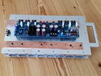
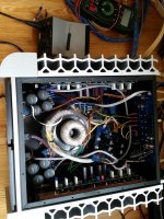
Since the Calaf originally has the big caps on the current gain boards; other caps are hard to retrofit.
Thus what you see is a Krelaf which is a mess. I will think about moving stuff around and maybe removing the original DC protection, which is not needed anymore.
Problem is that the protection board also has rectifiers and soft starter on it.
One thing, that is really asking for trouble, is that originally the thermal switches will only cut speaker output an not power in case of over heating!
In case of an internal fault (and not overload) nothing is there to save the amp!
I have not yet modified this on my amps, but I would also never leave the room with them on 😉
Attachments
Well. It turns out that after warming up the modified Calaf has like 20-30mA of BIAS per device with the trimpot set to 0ohms.
Thermal runaway does occur at some point. (such as yesterday)
What component would you suggest that I use for the compensation?
Something with a greater negative thermal coefficient than 1N4148.
I have seen NTC resistors being used, but smallest one I had was 4k7 so I would need to get smaller ones that can handle the 5-10mA without heating by themselves and thus decreasing bias too much.
Thanks in advance!
Yes, now I think it is stable.
I put a 2SD600 transistor + 330ohm & 3.3kohm resistors + 470ohm trimmer and got the bias very stable.
My old friend said to me: Jonas why won't you compensate bias as it is done in 95% of all amplifiers, with a transistor?
Turns out that was the working way.
If you want to do the same, I can send you photos.
Now when I got it working I can just assemble one original Calaf from the working boards I have and sell it. I'll keep the boards I tried modifications on. Or maybe sell them too.
Anybody want a Calaf?
It is nice and heavy, and sometimes a little bit reliable too 🙂
Sorry, as it was only 4 components I did not draw a schematic, just connect the resistors and transistor between pins 6 and 14 on JX2 and make sure the transistor is in thermal contact with heat sink. Have a peak at any normal class AB amp with bias compensation transistor when you feel unsure. That is how I did 🙂
Hope you get it working!
Hope you get it working!
Attachments

just so thanks this pdfSorry, as it was only 4 components I did not draw a schematic, just connect the resistors and transistor between pins 6 and 14 on JX2 and make sure the transistor is in thermal contact with heat sink. Have a peak at any normal class AB amp with bias compensation transistor when you feel unsure. That is how I did 🙂
Hope you get it working!
- Home
- Amplifiers
- Solid State
- Consonance Calaf, repairs and mods