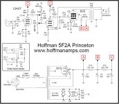
I've just finished up a 5F2A Princeton using the Hoffman schematic. I am using 6N6C and ECC83 tubes. PT is 220-0-220 diode rectified to get 315vdc.
When powered up, if I move the volume control more than about 20% off 0, the amp oscillates. The volume and tone pot varies the frequency of the oscillation.
The oscillation sounds like a trumpet / farty kind of sound.
I tried swapping the OT Primary leads and it oscillated from switch on and in a much more brutal way.
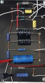
I poked around with chopsticks and rerouted the shielded cables (they are terminated one end only to the pot ground.
Firstly, do my voltages look ok?
B+ = 315
Bottom of 6V6 470R screen resistor (B) = 275
Top of 100K 12AX7 V1-B Anode Resister (C) = 270
6V6:
anode/plate = 300
Screen = 277
Grid = 3.5
Cathode = 20
Cathode R = 470
12AX7/ECC83
V1-A
Anode/plate = 260
Grid = 0
Cathode = 3.5
Cathode R = 1.5k
V1-B
Anode/plate = 250
Grid = 0
Cathode = 3.5
Cathode R = 1.5k
When powered up, if I move the volume control more than about 20% off 0, the amp oscillates. The volume and tone pot varies the frequency of the oscillation.
The oscillation sounds like a trumpet / farty kind of sound.
I tried swapping the OT Primary leads and it oscillated from switch on and in a much more brutal way.
I poked around with chopsticks and rerouted the shielded cables (they are terminated one end only to the pot ground.
Firstly, do my voltages look ok?
B+ = 315
Bottom of 6V6 470R screen resistor (B) = 275
Top of 100K 12AX7 V1-B Anode Resister (C) = 270
6V6:
anode/plate = 300
Screen = 277
Grid = 3.5
Cathode = 20
Cathode R = 470
12AX7/ECC83
V1-A
Anode/plate = 260
Grid = 0
Cathode = 3.5
Cathode R = 1.5k
V1-B
Anode/plate = 250
Grid = 0
Cathode = 3.5
Cathode R = 1.5k
Attachments
I tried swapping the OT Primary leads and it oscillated from switch on and in a much more brutal way.
Just on the subject of the OT, I used one with a 5k impedance. Google seemed to say this was ok for the 6V6.
The voltage on the 12AX7 cathodes are rather low, I would think they should be in the 1-1.5V range. This is why the plate voltages are so close to the supply. I would double check the resistance values of the cathode and plate resistors first off. Do you have a spare 12AX7?
With 3.5 V the 12AX7's cathode voltage are on the much too high side, I'd say. But this is in contradiction to the small 260 - 250 = 10 V difference across the plate resistors, corresponding to just 0.1 mA plate current. This leaves two options:
- measurement errors
- wrong plate and/or cathode resistors.
The tube itself doesn't appear to be faulty at this point, as for a (negatively biased) triode cathode and plate currents are expected to be identical.
Best regards!
- measurement errors
- wrong plate and/or cathode resistors.
The tube itself doesn't appear to be faulty at this point, as for a (negatively biased) triode cathode and plate currents are expected to be identical.
Best regards!
I should have mentioned that I transposed the 12ax7 for another if the same batch.
Could a low voltage at the preamp cause oscillations?
Could a low voltage at the preamp cause oscillations?
...if I move the volume control more than about 20% off 0, the amp oscillates....
Layout!
The huge signal from the OT plate lead is sneaking-back to the volume/tone area.
Hoffman has good drawings of known-good layouts. Do yours as close to his as you can. Even if it means major re-work.
Thanks, I'll put it down to a learning experience and redo the layout.
Thanks, that gives me an area to concentrate on.
The huge signal from the OT plate lead is sneaking-back to the volume/tone area.
Thanks, that gives me an area to concentrate on.
I have never had much success with the 12ax7. The mu is 100. I built a guitar amp and it oscillated badly despite being a no feedback amp. The second 12ax7 stage seemed to be feeding back into the first one somehow. The rails were decoupled separately so unless It was internal to the 12ax7 I don't know. I guess the 100 * 100 gain of the two 12ax7 stages which is 10000 was just far too much gain. A quick and simple bodge was to just replace 12ax7 with a 12au7 and that seemed to settle things down. The 12au7 is much smaller mu about 18.
I found layout was important keeping things as short as possible especially the input signal which should be screened where possible. Keep heater wires away from audio signal. Keep valves away from transformers. Route HVAC away from audio.
I have had troubles with hum but for some reason changing to DC never fixed it. SO AC heaters are ok if wires are routed well.
Last edited:
I have never had much success with the 12ax7. The mu is 100. I built a guitar amp and it oscillated badly despite being a no feedback amp. The second 12ax7 stage seemed to be feeding back into the first one somehow. The rails were decoupled separately so unless It was internal to the 12ax7 I don't know. I guess the 100 * 100 gain of the two 12ax7 stages which is 10000 was just far too much gain.
Unlikely. You'd need a plate load of unfinite impedance, e.g. a sophisticated CCS, to get a gain of 100. With a common resistor it always is lower than that.
Most probably your issue was the layout, too.
Best regards!
I don't know the schematic, but switching ultralinear leads will cause oscillation.
I also had a similar problem when I ran my feedback wires too close to the output tube wiring.
You can also try an external speaker in case it is caused by mechanical vibration and microphonics
I also had a similar problem when I ran my feedback wires too close to the output tube wiring.
You can also try an external speaker in case it is caused by mechanical vibration and microphonics
Last edited:
I agree with Kay Pirinha and Printer2. A 12AX7 is almost completely cut off with the cathode 3.5V volts more positive than the grid, and this is reflected in the very low voltage drop across the 100k anode load (270 V - 260 V). That means only 0.1 mA is flowing through each of the triodes, instead of the expected 1 mA.<snip>
Top of 100K 12AX7 V1-B Anode Resister (C) = 270
<snip>
12AX7/ECC83
V1-A
Anode/plate = 260
Grid = 0
Cathode = 3.5
Cathode R = 1.5k
V1-B
Anode/plate = 250
Grid = 0
Cathode = 3.5
Cathode R = 1.5k
Have you checked - with power off - the resistance from the 12AX7's pin 3 to ground, and also pin 8 to ground?
I bet you will measure something much bigger than the expected 1.5k. Either those 1.5k resistors aren't actually 1.5k (maybe they're 15k?), or there is a missing ground wire, or a bad solder joint.
This may not be the only problem you are facing, but clearly, DC operating conditions for the 12AX7 are very wrong, so that needs to be fixed before further trouble-shooting is done.
-Gnobuddy
...cathode 3.5V volts more positive than the grid, ...aren't actually 1.5k (maybe they're 15k?)...
Yes, that; but he says it oscillates. HIGH grid drive tries to take grid positive, can't, and the input R-C charges-down to a negative voltage.
Ha, but he shows zero at grid? Well, maybe it quits oscillating when he puts the probe on the grid, capacitive loading. With two meters he could watch the cathode voltage recover while he pokes the grid.
V1A has no input cap, but I suppose the cathode resistor could charge positive instead, with the valve operating nearly in class C.the input R-C charges-down to a negative voltage.
Mebbe measure DC voltages with volume turned down to zero? OP reports no (audible) oscillation with the volume down.
-Gnobuddy
> V1A has no input cap
V1b does; I just noticed your #14 does not specify.
ALSO: same 3.5V on *both* stages. Guessing on thumbs, it could be a 12AY7 or 12AT7, not ECC83/12AX7.
V1b does; I just noticed your #14 does not specify.
ALSO: same 3.5V on *both* stages. Guessing on thumbs, it could be a 12AY7 or 12AT7, not ECC83/12AX7.
> V1A has no input cap
V1b does; I just noticed your #14 does not specify.
ALSO: same 3.5V on *both* stages. Guessing on thumbs, it could be a 12AY7 or 12AT7, not ECC83/12AX7.
The tubes are all marked 'Marshall ECC 83' so I assume they are as advertised.. Hopefully...
V1A has no input cap, but I suppose the cathode resistor could charge positive instead, with the valve operating nearly in class C.
Mebbe measure DC voltages with volume turned down to zero? OP reports no (audible) oscillation with the volume down.
The measurements were taken with the volume set to just under the oscillating point IIRC. I'll try take another set with volume definitely at 0 when I get back (I'm outta town at the mo).
I agree with Kay Pirinha and Printer2. A 12AX7 is almost completely cut off with the cathode 3.5V volts more positive than the grid, and this is reflected in the very low voltage drop across the 100k anode load (270 V - 260 V). That means only 0.1 mA is flowing through each of the triodes, instead of the expected 1 mA.
Have you checked - with power off - the resistance from the 12AX7's pin 3 to ground, and also pin 8 to ground?
I bet you will measure something much bigger than the expected 1.5k. Either those 1.5k resistors aren't actually 1.5k (maybe they're 15k?), or there is a missing ground wire, or a bad solder joint.
Thanks, I'll make those measurements. I did check that the resistors were indeed 1k5 but I shall check the run from 3 and 8 to ground to be sure there isn't a missing solder blob...
In the meantime, I will also tidy up the wiring to be certain that the Outputs are well clear of the Inputs.
Am I right that the heater leads should be routed through the centre of the valve socket rather than each lead coming around either side?
- Status
- Not open for further replies.
- Home
- Live Sound
- Instruments and Amps
- So I made an oscillator! Now what..?